# RF Tap Installation Guide
Next Page [The RF Capture Guide](RF-Capture-Guide)
Sub-Page [Selecting Capture Hardware](Workflow-Guide)
Sub-Page [Troubleshooting Guide](Troubleshooting-Guide)
Previous Page [The Tap List](004-The-Tap-List)
## Table of Contents
- [First please look at The Tap list Example VCR's](#first-please-look-at-the-tap-list-example-vcrs)
- [Helpful Videos for Absolute Beginners](#helpful-videos-for-absolute-beginners)
- [Tooling \& Equipment](#tooling--equipment)
- [Essentials](#essentials)
- [Advanced Tools](#advanced-tools)
- [Cleaning Supplies](#cleaning-supplies)
- [Maintenance Supplies](#maintenance-supplies)
- [Step 00: Inspect \& Clean Your Device](#step-00-inspect--clean-your-device)
- [Step 01: Find FM RF Test Points](#step-01-find-fm-rf-test-points)
- [Step 02: Cabling \& Planning](#step-02-cabling--planning)
- [Step 03: Mounting \& Routing](#step-03-mounting--routing)
- [Step 04: Stripping \& Soldering Cables](#step-04-stripping--soldering-cables)
- [Step 05: Installing a capacitor on your RF tap](#step-05-installing-a-capacitor-on-your-rf-tap)
- [Step 06: Amplifier Setup](#step-06-amplifier-setup)
- [RF Tap Setup Examples](#rf-tap-setup-examples)
- [Connect your RF Capture Device & Capture!](#connect-your-rf-capture-device--capture)
- [DdD](#ddd)
- [CX Cards](#cx-cards)
- [Clockgen Mod](#clockgen-mod)
# [First please look at The Tap list Example VCR's](004-The-Tap-List)
Firstly see if your VCR or similar has been added to [the tap list](004-The-Tap-List) or just want real-world visual examples of tapped decks, below is the methods we use, but the guide overall focuses on basic soldering which has the most use from both a RF Tapping but also a basic repair skill perspective.
## Soldering-Free Setups
While soldering is **encouraged and quite easy in practice** as the vast majority of VCRs without 2.54mm headers have easy to get at standard bar/floating bar test points, so the soldering method allows for 99% of decks to be tapped for RF capture, but the need to directly solder onto a VCR is not always required however it can make a clean and practical upgrade with safe locking BNC ports at the back.
It can be scary to some and to get started, we understand some people might not want to take an iron to their VCR, especially a higher-end one without practising basic soldering beforehand.
So reading this doc fully is highly recommended, however either way you go a clean setup requires proper cables and a proper electrical connection and soldering and melting/drilling a hole and adding a bulkhead protects the internal test points from snagged cables and the like.
Either way you go however this **does not mean** you can neglect the basics of cleaning VCR heads, drums, guides and checking it over, as it's a electromechanical system, just like a car or any other tool it requires some level of care, such as re-lubrication and regular cleaning please read the [Cleaning & Servicing Guide](Cleaning-&-Servicing-Guide) regardless if you're deploying FM RF capture workflows or not.
--------------------
### Soldered Method
This involves simple non-complex surface soldering of a signal and a ground wire (or centre wire and outer braid for the coax type used here) from test points or head pre-amplifier pins/legs.
This can be Direct --> Capacitor --> BNC Bulkhead.
Direct --> [ADA4857](amplifier-setup-guide) --> BNC Bulkhead.
The original 2020s typical setup was a 3.3~10uf range capacitor in-line to limit signal draw to allow normal stable playback for real-time reference capture during RF capture. Now 10uf caps are standard on the [ADA4857](amplifier-setup-guide) amplifier; it's now a non-critical thing. Of note, the amplifier uses internal deck power but can also take separate DC battery power.
> [!NOTE]
> This example is a test point tap, with only a 10uf cap added in-line.
 > [!NOTE]
> This example is a test point tap going to an [ADA4857](amplifier-setup-guide) amplifier.
>
> [!NOTE]
> This example is a test point tap going to an [ADA4857](amplifier-setup-guide) amplifier.
>
 > Yes you can remove the TV Pack with desoldering and use its pins for power and its holes for bulkheads!
-------------------
## DuPont Pin Method
Sony decks normally have 2.54mm pin-header test points
(These cables can be made at home with RG316 & 26 AWG copper wire via soldering iron, crimper & heat shrink)
[DuPont Female to BNC](https://s.click.aliexpress.com/e/_DBXtcM3) / [DuPont Male to BNC](https://s.click.aliexpress.com/e/_DldgSHV) / [SMA to DuPont Female](https://s.click.aliexpress.com/e/_DdLP7v1) adapters.
[Example](https://github.com/oyvindln/vhs-decode/wiki/004-The-Tap-List#sony-slv-677hf) (This applies to VHS/Beta/Video8/High8)
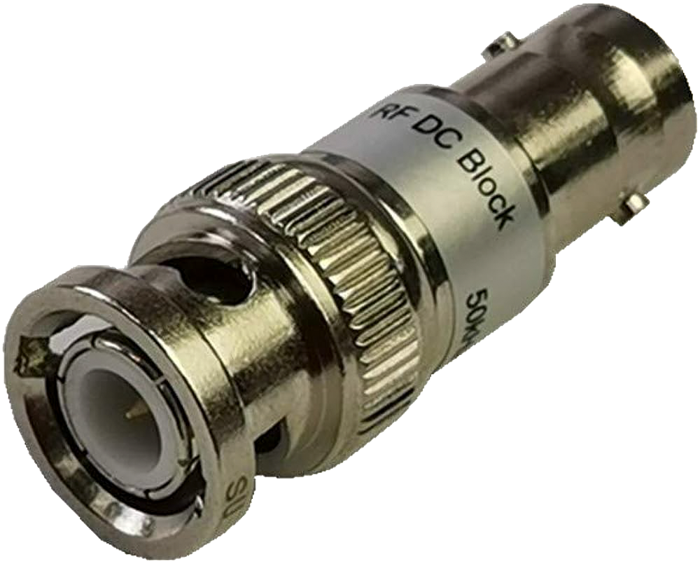
If you go the Dupont pin method use an In-line Capacitor (Limits signal draw to allow for live playback alongside RF capture) [AliExpress](https://s.click.aliexpress.com/e/_DCag1dt) / [Amazon US](https://www.amazon.com/DC-Block-Connector-Include-SMA-MF-50KHz-8GHz/dp/B07JR5ZNW7)
> Yes you can remove the TV Pack with desoldering and use its pins for power and its holes for bulkheads!
-------------------
## DuPont Pin Method
Sony decks normally have 2.54mm pin-header test points
(These cables can be made at home with RG316 & 26 AWG copper wire via soldering iron, crimper & heat shrink)
[DuPont Female to BNC](https://s.click.aliexpress.com/e/_DBXtcM3) / [DuPont Male to BNC](https://s.click.aliexpress.com/e/_DldgSHV) / [SMA to DuPont Female](https://s.click.aliexpress.com/e/_DdLP7v1) adapters.
[Example](https://github.com/oyvindln/vhs-decode/wiki/004-The-Tap-List#sony-slv-677hf) (This applies to VHS/Beta/Video8/High8)
If you go the Dupont pin method use an In-line Capacitor (Limits signal draw to allow for live playback alongside RF capture) [AliExpress](https://s.click.aliexpress.com/e/_DCag1dt) / [Amazon US](https://www.amazon.com/DC-Block-Connector-Include-SMA-MF-50KHz-8GHz/dp/B07JR5ZNW7)
 --------
## Jig Method Video8 & Hi8
--------
## Jig Method Video8 & Hi8
 ### [Dedicated Sony 8mm Page](Sony-8mm-Formats)
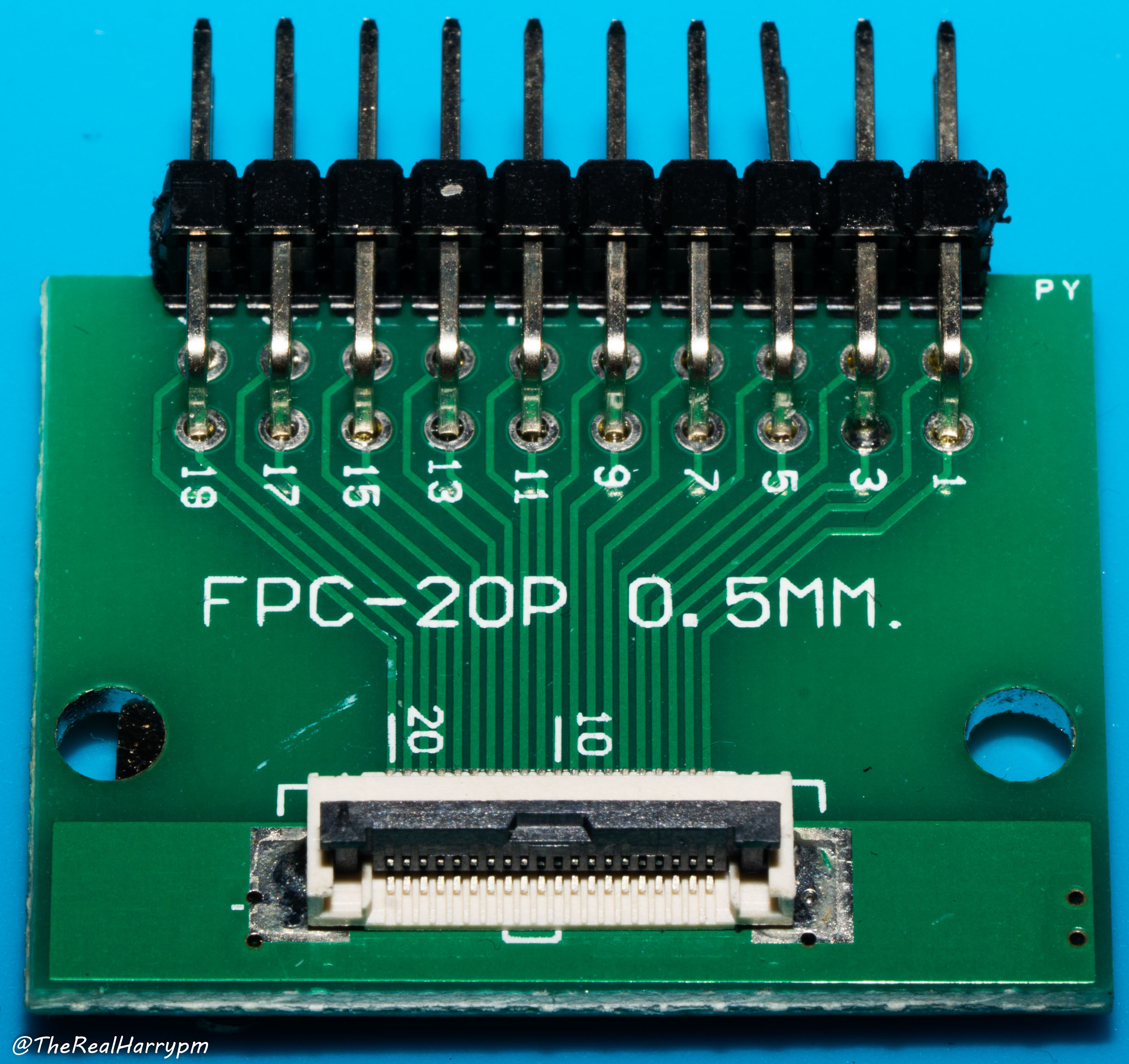
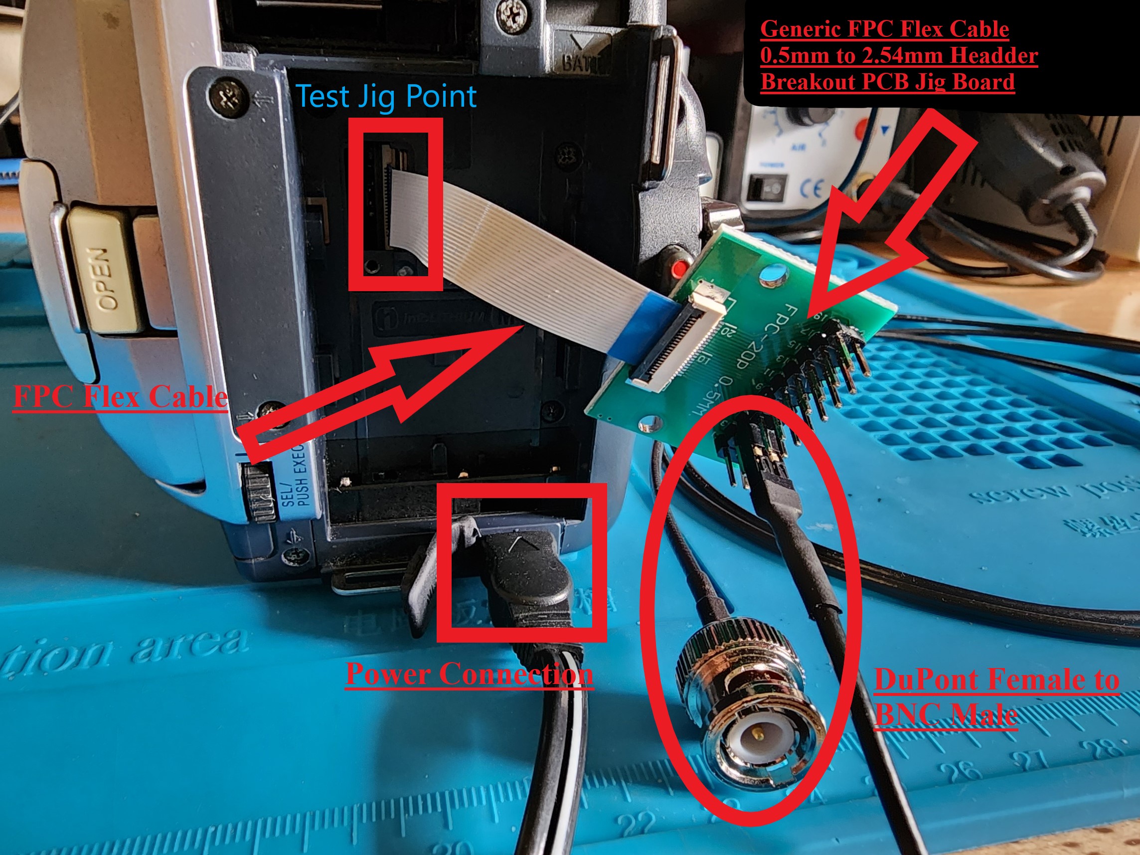
On most Sony Video8, Hi8 and later Digital8 camcorders that had support backwards playback, at the battery area, there is a cover plate with a single screw, once removed this exposes the Jig connection point for testing this is normally 16/18/20 pin FPC type connector with a 0.5mm pitch, with is readily available and generic cables & jigs being off-shelf parts.
This is the go-to method for Video8/Hi8 tape formats, RF capture also only requires 1 ADC like LaserDisc.
Simply visually check your pin amount and buy the correct jig with the links below.
Check the service manual to see what pins have the RF signal, and you're ready to go, however a capacitor may be needed in-line like any RF capture method.
[Jigs (Unpopulated)](https://s.click.aliexpress.com/e/_DDzalwj) / [Jigs (With 2.54mm pins)](https://s.click.aliexpress.com/e/_DkZFTVv) / [Flex Cable 0.5mm Pitch](https://s.click.aliexpress.com/e/_DD5gRMR) / [DuPont to BNC](https://s.click.aliexpress.com/e/_DBDAGXp) [Type 2 AC-L200 USB Power Adapter](https://s.click.aliexpress.com/e/_DkeCeDl) / [Type 1 AC-L100 USB Power Adapter](https://s.click.aliexpress.com/e/_Dkyoi6R)
---------------------
## BNC Probe Method
BNC probes can be used for a solderless hook-up, but may not have as reliable signal and can easily be knocked free, unlike a soldered and mounted RF Tap. Alternatively, standard Oscilloscope probes set to 1x mode can also be used this manner as they also use standard BNC Connectors. Oscilloscope probes will give some guarantee that the wires and probes are high quality though the probes themselves can also be a bit long and impractical.
- [BNC Alligator](https://s.click.aliexpress.com/e/_DFOdQpd)
- [BNC Hook](https://s.click.aliexpress.com/e/_DDhV15p)
- [BNC Probe](https://s.click.aliexpress.com/e/_DCKVOqf)
- [BNC Banana](https://s.click.aliexpress.com/e/_DmMXh1D) + [Banana Pin Probes](https://s.click.aliexpress.com/e/_DmwjU0L)
### [Dedicated Sony 8mm Page](Sony-8mm-Formats)
On most Sony Video8, Hi8 and later Digital8 camcorders that had support backwards playback, at the battery area, there is a cover plate with a single screw, once removed this exposes the Jig connection point for testing this is normally 16/18/20 pin FPC type connector with a 0.5mm pitch, with is readily available and generic cables & jigs being off-shelf parts.
This is the go-to method for Video8/Hi8 tape formats, RF capture also only requires 1 ADC like LaserDisc.
Simply visually check your pin amount and buy the correct jig with the links below.
Check the service manual to see what pins have the RF signal, and you're ready to go, however a capacitor may be needed in-line like any RF capture method.
[Jigs (Unpopulated)](https://s.click.aliexpress.com/e/_DDzalwj) / [Jigs (With 2.54mm pins)](https://s.click.aliexpress.com/e/_DkZFTVv) / [Flex Cable 0.5mm Pitch](https://s.click.aliexpress.com/e/_DD5gRMR) / [DuPont to BNC](https://s.click.aliexpress.com/e/_DBDAGXp) [Type 2 AC-L200 USB Power Adapter](https://s.click.aliexpress.com/e/_DkeCeDl) / [Type 1 AC-L100 USB Power Adapter](https://s.click.aliexpress.com/e/_Dkyoi6R)
---------------------
## BNC Probe Method
BNC probes can be used for a solderless hook-up, but may not have as reliable signal and can easily be knocked free, unlike a soldered and mounted RF Tap. Alternatively, standard Oscilloscope probes set to 1x mode can also be used this manner as they also use standard BNC Connectors. Oscilloscope probes will give some guarantee that the wires and probes are high quality though the probes themselves can also be a bit long and impractical.
- [BNC Alligator](https://s.click.aliexpress.com/e/_DFOdQpd)
- [BNC Hook](https://s.click.aliexpress.com/e/_DDhV15p)
- [BNC Probe](https://s.click.aliexpress.com/e/_DCKVOqf)
- [BNC Banana](https://s.click.aliexpress.com/e/_DmMXh1D) + [Banana Pin Probes](https://s.click.aliexpress.com/e/_DmwjU0L)
 -------------------
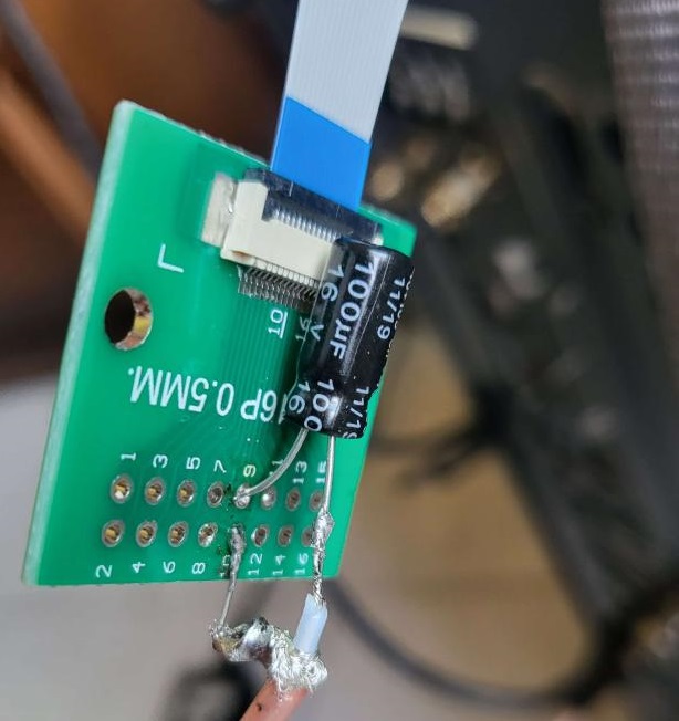
### Pushpin Method
The pin push method is simply just wedging a capacitor leg into the FPC or flex connector pins. This middle-man approach allows you to solder to the exterior grounding shield and not touch any valuable components with the iron on decks with external head amplifier modules.
> [!WARNING]
> This can easily damage FPC pins if not aligned properly and is recommended to just solder (or use test points), as it's easier to shield the taps within a head amplifier module.
-------------------
### Pushpin Method
The pin push method is simply just wedging a capacitor leg into the FPC or flex connector pins. This middle-man approach allows you to solder to the exterior grounding shield and not touch any valuable components with the iron on decks with external head amplifier modules.
> [!WARNING]
> This can easily damage FPC pins if not aligned properly and is recommended to just solder (or use test points), as it's easier to shield the taps within a head amplifier module.
 # Helpful Videos for Absolute Beginners
- [The NASA Standard of Soldering](https://www.youtube.com/watch?v=_RXugDd0xik)
- [Beginner's Guide to Soldering Electronics](https://www.youtube.com/watch?v=M2Jf8cebwCs)
- [Electronoobs SMD Soldering Guide](https://www.youtube.com/watch?v=fYInlAmPnGo&t)
- [Electrical Components Guide](https://www.youtube.com/watch?v=6Maq5IyHSuc)
- [Comprehensive Micro Soldering Guide](https://www.youtube.com/watch?v=zgAKy6vBiv4)
How to use a Digital Multi Meter (DMM):
- [Voltage Measurement & Basic Usage](https://www.youtube.com/watch?v=ZBbgiBU96mM)
- [Current Measurement](https://www.youtube.com/watch?v=EVFkKBFJsZg)
- [Resistance & Continuity](https://www.youtube.com/watch?v=InJhgwmj2So)
# Tooling & Equipment
You will need the following items
## Essentials
- [JIS & Flathead](https://s.click.aliexpress.com/e/_DenYmFD) Standard screwdrivers (JIS are more ideal than Phillips due to head-stripping issues)
- [JIS Precision Screwdrivers](https://s.click.aliexpress.com/e/_DejFcZd) (Camcorders/Anything Japanese OEM)
- [U-Bit Set](https://s.click.aliexpress.com/e/_c4mWUQ2F) for VHS/Beta etc Head Posts.
- [Side Cutters](https://s.click.aliexpress.com/e/_DBq028L) or [Flush Cutters](https://s.click.aliexpress.com/e/_c3luutOb) / Sharp Scissors / [Automatic Wire Strippers](https://s.click.aliexpress.com/e/_DDPkn8P)
- Soldering Iron (portable DC/USB PD powered) like the modern, such as [PINECIL](https://s.click.aliexpress.com/e/_DErI1KT) / [Square S99](https://s.click.aliexpress.com/e/_c2JAMir5) / [FNIRSI HS-02](https://s.click.aliexpress.com/e/_oBxZe25) & [YIHUA 928D-IV C235](https://s.click.aliexpress.com/e/_op3hRCN) (Portable irons are using C245/C210 tips now much quicker heating then TS100 style)
- Soldering Iron (station) such as the JBC tip taking [GMV H3](https://s.click.aliexpress.com/e/_c4qXSM75) or [GEEBOON TC22](https://www.aliexpress.com/item/1005006397758007.html) (C245 for standard use, C210 and C115 for micro soldering)
- USB Type-C PD 65~140w [Power Hubs](https://s.click.aliexpress.com/e/_onoVj45) (with 3 pin earthing to ground) or PD [65w](https://s.click.aliexpress.com/e/_DmCxXZl) / [100w](https://s.click.aliexpress.com/e/_DClD5Jh) / [140w](https://s.click.aliexpress.com/e/_DlkSIYl) Power Banks / [12~24v Car Adapters](https://s.click.aliexpress.com/e/_DFUwXPh).
- [Heat Shrink](https://s.click.aliexpress.com/e/_DebWKMn) / [Electrical Tape](https://s.click.aliexpress.com/e/_DlpLeLV) / [Hot-Glue](https://www.aliexpress.com/item/32989692608.html?) / [Silicone Sealant (Clear/Translucent)](https://s.click.aliexpress.com/e/_c4qywq91) (For insulating cables and connections)
- [A Basic True RMS Digital Multi Meter](https://s.click.aliexpress.com/e/_om9vfcn) (DMM) (or look at the OWON combi units mentioned below as they are very good DMM units)
- [Proper probes for any multimeter](https://s.click.aliexpress.com/e/_c30JF4mb) (Sharp and replaceable tip probes are a go-to for fine component work, also wire-insulation stab probing)
## Advanced Tools
Worth it for anything related to electronic's work, and can make life a lot easier for servicing and fine-tuning.
- Soldering Tweezers [SEQURE HT140 (DC/PD)](https://s.click.aliexpress.com/e/_opR28fP) & [YIHUA 938D (AC Only)](https://s.click.aliexpress.com/e/_oog0ech)
(These make life much less painful when removing or populating SMD parts such as on the [ADA4857 amplifier](Amplifier-Setup-Guide))
- LCR readers [Dedicated](https://s.click.aliexpress.com/e/_DEeW5Zb) / [Tweezer](https://s.click.aliexpress.com/e/_oliewJx)
- Analog Benchtop Oscilloscope (20-40mhz)
- Digital storage oscilloscope (40–200 MHz)
The [Rigol DHO804](https://s.click.aliexpress.com/e/_c3DLRROB) is recommended as the best value modern benchtop DSO type oscilloscope, as not only is it compact, but can be [Firmware/Hardware upgraded](https://docs.google.com/document/d/1m4uu2SbBgG5H5snbT8Sr1aPApiKY-61r_LGc-mkIq_A/edit?usp=sharing) to the 925S model for 1/5th the cost. With the base DHO804 coming in at under 300USD globally during sales.
Modern Combo DMMs (True RMS Digital Multimeter + Oscilloscope + Signal Generator) save a lot of space and have great multi-use value, but are a "jack of all trades" device.
The [OWON HDS2202S](https://www.owon.com.hk/products_owon_hds200_series_digital_oscilloscope) / [Link 1](https://s.click.aliexpress.com/e/_DewP2ef) / [Link 2](https://s.click.aliexpress.com/e/_c3Uac1BZ) / [Screen Protector](https://www.ebay.com/itm/363616997950) / [8000mAh Battery Upgrade](https://s.click.aliexpress.com/e/_olgOldN) is an all-in-one unit recommendation as the entire line-up has almost everything feature-wise needed at a reasonable price point but has one key feature over most others in the market, a bright and daylight usable display. Of course, the lower end models are also cheaper, but the 100/200mhz versions are the most useful.
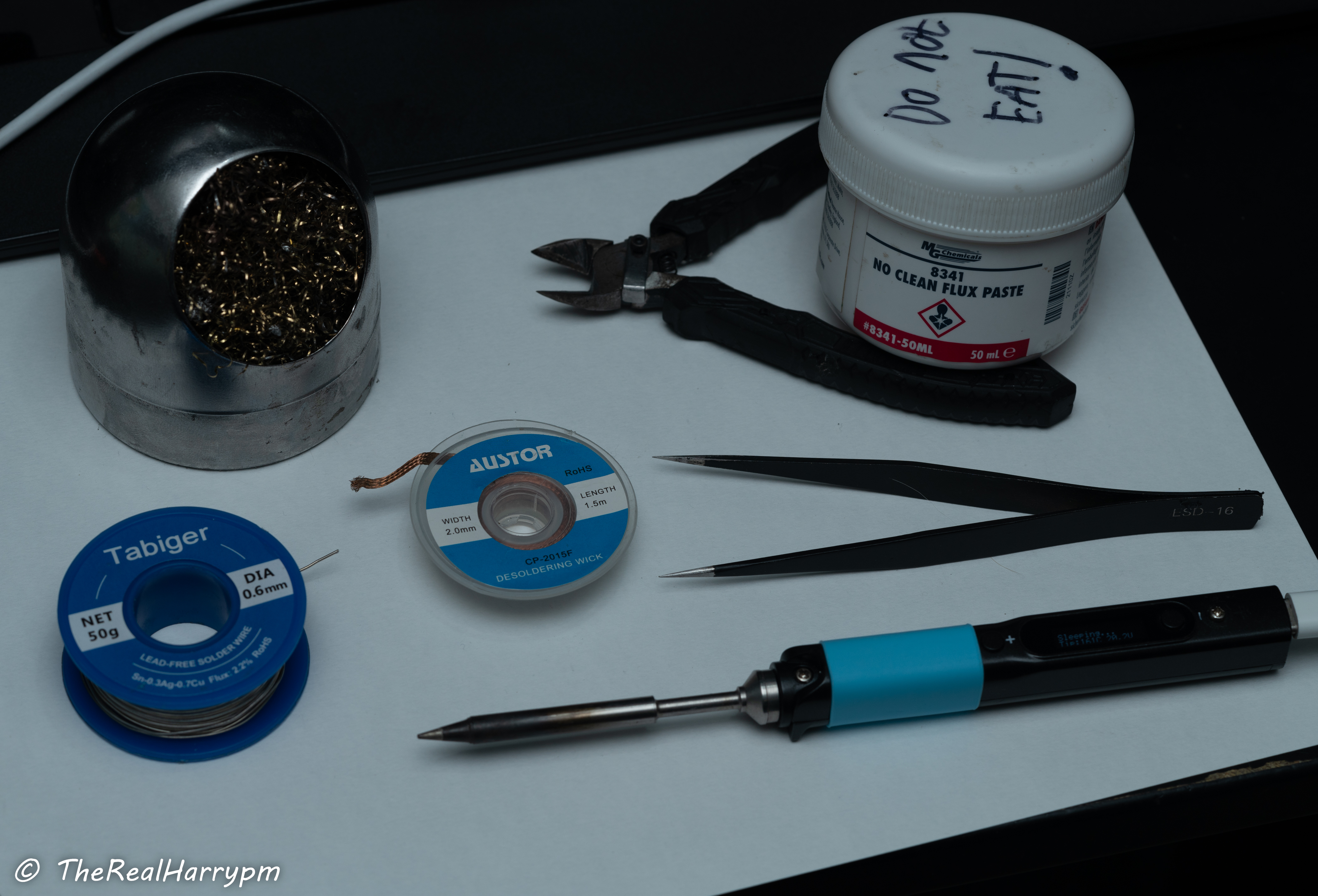
## Building a Soldering Kit
- Sn 63/37 Pb leaded (0.8 mm) - [Mechanic SX-862](https://s.click.aliexpress.com/e/_c4lfQenz) or [MECHANIC HX-T100](https://s.click.aliexpress.com/e/_oozJx6h) (Good quality and better melting point than 60/40)
- [M35 Clear Flux Paste (Mechanic)](https://s.click.aliexpress.com/e/_oC65Tpf) / [Amaoe M50/M53](https://s.click.aliexpress.com/e/_c3rGNJmJ)
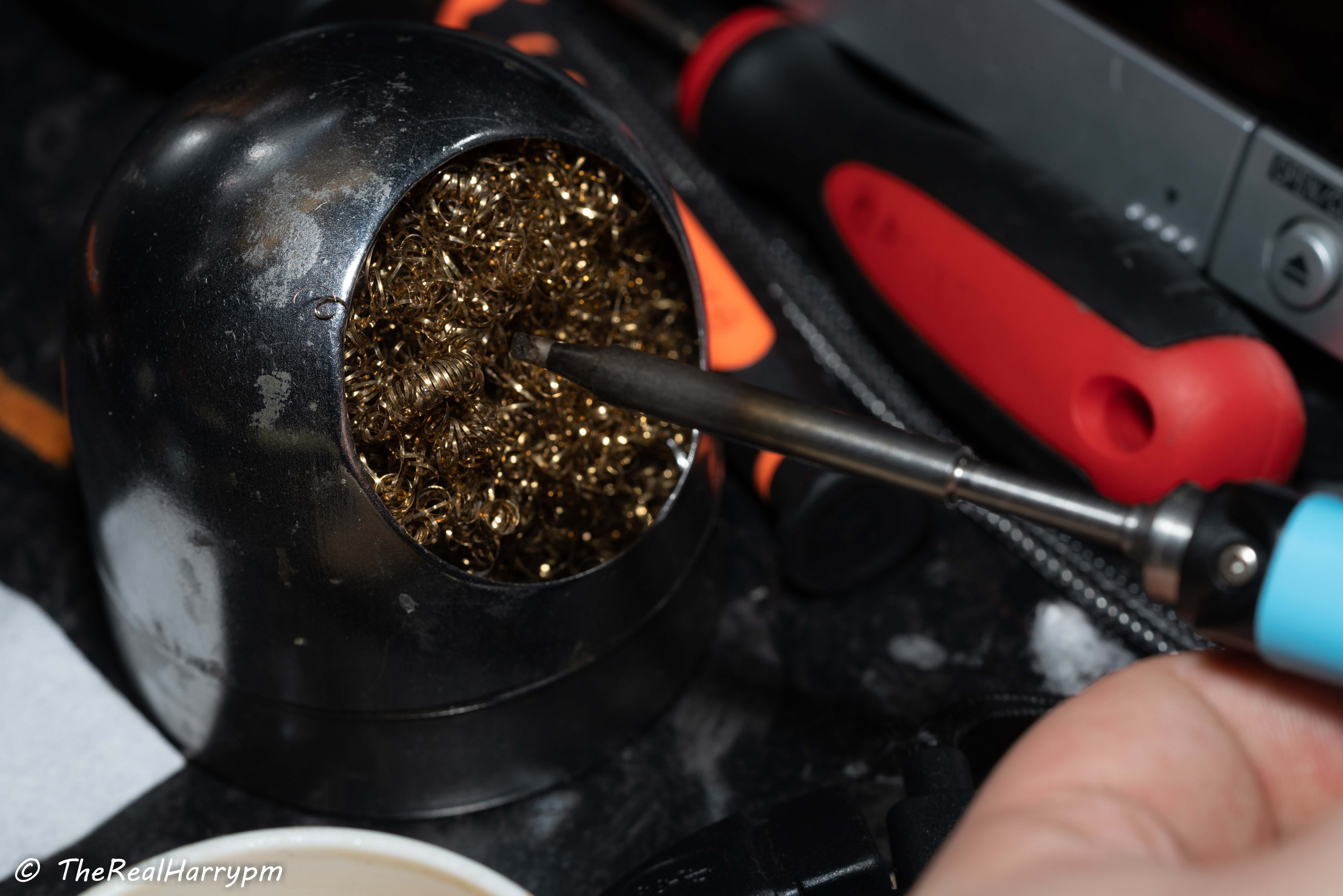
- [Brass Wire ball cleaner](https://s.click.aliexpress.com/e/_DDkeQXt) / [Brass Wire Puck](https://s.click.aliexpress.com/e/_c2ucRwYn)
- [Hakko-FH300 Iron Holder](https://www.google.com/search?q=hakko+FH+300)
> [!TIP]
> - A clean & tinned soldering tip, is a happy long-lasting tip.
> - Sponge cleaners will thermally damage tips, stick to using brass wire ball style cleaners as much as possible.
- [Solder Wicking](https://s.click.aliexpress.com/e/_DFOmsTD) - Generic or SuperWick/GootWick
- Chisel and Bevel Type Tips for your iron.
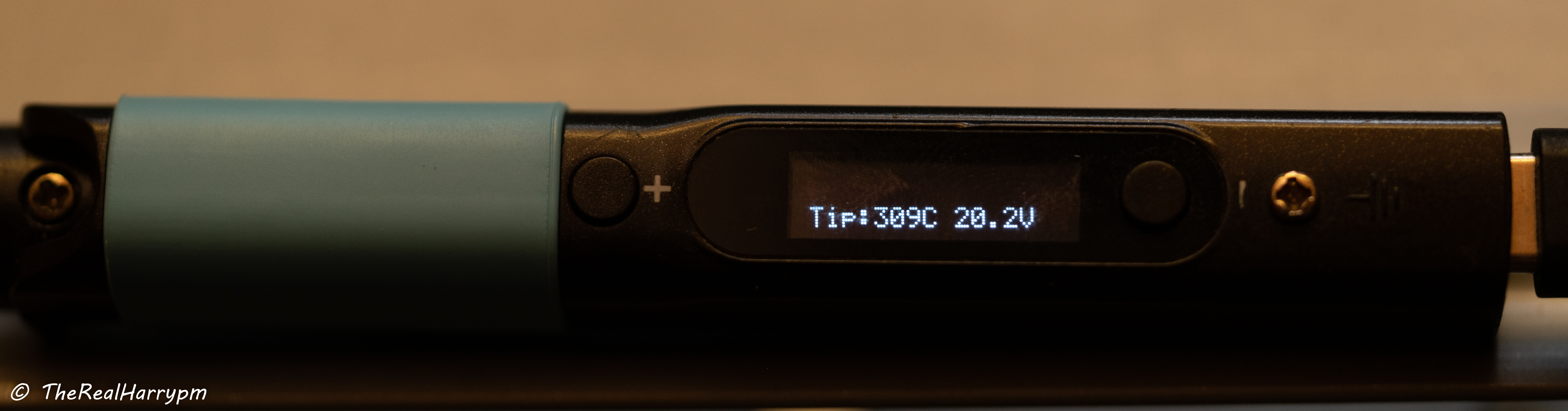
Here's the PINECIL with a built-up kit.
# Helpful Videos for Absolute Beginners
- [The NASA Standard of Soldering](https://www.youtube.com/watch?v=_RXugDd0xik)
- [Beginner's Guide to Soldering Electronics](https://www.youtube.com/watch?v=M2Jf8cebwCs)
- [Electronoobs SMD Soldering Guide](https://www.youtube.com/watch?v=fYInlAmPnGo&t)
- [Electrical Components Guide](https://www.youtube.com/watch?v=6Maq5IyHSuc)
- [Comprehensive Micro Soldering Guide](https://www.youtube.com/watch?v=zgAKy6vBiv4)
How to use a Digital Multi Meter (DMM):
- [Voltage Measurement & Basic Usage](https://www.youtube.com/watch?v=ZBbgiBU96mM)
- [Current Measurement](https://www.youtube.com/watch?v=EVFkKBFJsZg)
- [Resistance & Continuity](https://www.youtube.com/watch?v=InJhgwmj2So)
# Tooling & Equipment
You will need the following items
## Essentials
- [JIS & Flathead](https://s.click.aliexpress.com/e/_DenYmFD) Standard screwdrivers (JIS are more ideal than Phillips due to head-stripping issues)
- [JIS Precision Screwdrivers](https://s.click.aliexpress.com/e/_DejFcZd) (Camcorders/Anything Japanese OEM)
- [U-Bit Set](https://s.click.aliexpress.com/e/_c4mWUQ2F) for VHS/Beta etc Head Posts.
- [Side Cutters](https://s.click.aliexpress.com/e/_DBq028L) or [Flush Cutters](https://s.click.aliexpress.com/e/_c3luutOb) / Sharp Scissors / [Automatic Wire Strippers](https://s.click.aliexpress.com/e/_DDPkn8P)
- Soldering Iron (portable DC/USB PD powered) like the modern, such as [PINECIL](https://s.click.aliexpress.com/e/_DErI1KT) / [Square S99](https://s.click.aliexpress.com/e/_c2JAMir5) / [FNIRSI HS-02](https://s.click.aliexpress.com/e/_oBxZe25) & [YIHUA 928D-IV C235](https://s.click.aliexpress.com/e/_op3hRCN) (Portable irons are using C245/C210 tips now much quicker heating then TS100 style)
- Soldering Iron (station) such as the JBC tip taking [GMV H3](https://s.click.aliexpress.com/e/_c4qXSM75) or [GEEBOON TC22](https://www.aliexpress.com/item/1005006397758007.html) (C245 for standard use, C210 and C115 for micro soldering)
- USB Type-C PD 65~140w [Power Hubs](https://s.click.aliexpress.com/e/_onoVj45) (with 3 pin earthing to ground) or PD [65w](https://s.click.aliexpress.com/e/_DmCxXZl) / [100w](https://s.click.aliexpress.com/e/_DClD5Jh) / [140w](https://s.click.aliexpress.com/e/_DlkSIYl) Power Banks / [12~24v Car Adapters](https://s.click.aliexpress.com/e/_DFUwXPh).
- [Heat Shrink](https://s.click.aliexpress.com/e/_DebWKMn) / [Electrical Tape](https://s.click.aliexpress.com/e/_DlpLeLV) / [Hot-Glue](https://www.aliexpress.com/item/32989692608.html?) / [Silicone Sealant (Clear/Translucent)](https://s.click.aliexpress.com/e/_c4qywq91) (For insulating cables and connections)
- [A Basic True RMS Digital Multi Meter](https://s.click.aliexpress.com/e/_om9vfcn) (DMM) (or look at the OWON combi units mentioned below as they are very good DMM units)
- [Proper probes for any multimeter](https://s.click.aliexpress.com/e/_c30JF4mb) (Sharp and replaceable tip probes are a go-to for fine component work, also wire-insulation stab probing)
## Advanced Tools
Worth it for anything related to electronic's work, and can make life a lot easier for servicing and fine-tuning.
- Soldering Tweezers [SEQURE HT140 (DC/PD)](https://s.click.aliexpress.com/e/_opR28fP) & [YIHUA 938D (AC Only)](https://s.click.aliexpress.com/e/_oog0ech)
(These make life much less painful when removing or populating SMD parts such as on the [ADA4857 amplifier](Amplifier-Setup-Guide))
- LCR readers [Dedicated](https://s.click.aliexpress.com/e/_DEeW5Zb) / [Tweezer](https://s.click.aliexpress.com/e/_oliewJx)
- Analog Benchtop Oscilloscope (20-40mhz)
- Digital storage oscilloscope (40–200 MHz)
The [Rigol DHO804](https://s.click.aliexpress.com/e/_c3DLRROB) is recommended as the best value modern benchtop DSO type oscilloscope, as not only is it compact, but can be [Firmware/Hardware upgraded](https://docs.google.com/document/d/1m4uu2SbBgG5H5snbT8Sr1aPApiKY-61r_LGc-mkIq_A/edit?usp=sharing) to the 925S model for 1/5th the cost. With the base DHO804 coming in at under 300USD globally during sales.
Modern Combo DMMs (True RMS Digital Multimeter + Oscilloscope + Signal Generator) save a lot of space and have great multi-use value, but are a "jack of all trades" device.
The [OWON HDS2202S](https://www.owon.com.hk/products_owon_hds200_series_digital_oscilloscope) / [Link 1](https://s.click.aliexpress.com/e/_DewP2ef) / [Link 2](https://s.click.aliexpress.com/e/_c3Uac1BZ) / [Screen Protector](https://www.ebay.com/itm/363616997950) / [8000mAh Battery Upgrade](https://s.click.aliexpress.com/e/_olgOldN) is an all-in-one unit recommendation as the entire line-up has almost everything feature-wise needed at a reasonable price point but has one key feature over most others in the market, a bright and daylight usable display. Of course, the lower end models are also cheaper, but the 100/200mhz versions are the most useful.
## Building a Soldering Kit
- Sn 63/37 Pb leaded (0.8 mm) - [Mechanic SX-862](https://s.click.aliexpress.com/e/_c4lfQenz) or [MECHANIC HX-T100](https://s.click.aliexpress.com/e/_oozJx6h) (Good quality and better melting point than 60/40)
- [M35 Clear Flux Paste (Mechanic)](https://s.click.aliexpress.com/e/_oC65Tpf) / [Amaoe M50/M53](https://s.click.aliexpress.com/e/_c3rGNJmJ)
- [Brass Wire ball cleaner](https://s.click.aliexpress.com/e/_DDkeQXt) / [Brass Wire Puck](https://s.click.aliexpress.com/e/_c2ucRwYn)
- [Hakko-FH300 Iron Holder](https://www.google.com/search?q=hakko+FH+300)
> [!TIP]
> - A clean & tinned soldering tip, is a happy long-lasting tip.
> - Sponge cleaners will thermally damage tips, stick to using brass wire ball style cleaners as much as possible.
- [Solder Wicking](https://s.click.aliexpress.com/e/_DFOmsTD) - Generic or SuperWick/GootWick
- Chisel and Bevel Type Tips for your iron.
Here's the PINECIL with a built-up kit.
 > [!WARNING]
> You will want to consider an extractor or respirator for soldering. Flux fumes (not lead) are much more harmful than alcohol vapours and/or second-hand smoke.
[Basic Carbon / P3 air scrubber](https://s.click.aliexpress.com/e/_oFDxMSN) (block all sides but one facing your workspace for maximum static pressure)
### Extra tools
- [3rd Arm Holder](https://s.click.aliexpress.com/e/_De9pRzp)
- [Extractor](https://s.click.aliexpress.com/e/_Depbvlv) / [Extra Filters](https://s.click.aliexpress.com/e/_De2KoDN)
- [Hot Air Station](https://s.click.aliexpress.com/e/_DEwgSIR)
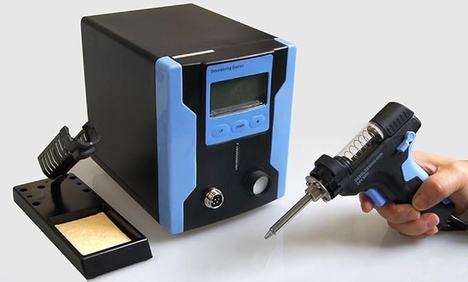
A fancy but immensely lifespan-saving item is a desoldering vacuum station. If you ever plan to remove THT/through-hole components, this will save your parts and your solder pads from damage, and is a lot less wrist strain compared to a spring-loaded solder sucker (which is only practical if low-melt/low-temperature solder is added to the joint first).
- [KATSU / ProsKit Desoldering Station](https://s.click.aliexpress.com/e/_De48dcf) / [Video Demo](https://www.youtube.com/watch?app=desktop&v=tfuXHNDy3zU)
> [!WARNING]
> You will want to consider an extractor or respirator for soldering. Flux fumes (not lead) are much more harmful than alcohol vapours and/or second-hand smoke.
[Basic Carbon / P3 air scrubber](https://s.click.aliexpress.com/e/_oFDxMSN) (block all sides but one facing your workspace for maximum static pressure)
### Extra tools
- [3rd Arm Holder](https://s.click.aliexpress.com/e/_De9pRzp)
- [Extractor](https://s.click.aliexpress.com/e/_Depbvlv) / [Extra Filters](https://s.click.aliexpress.com/e/_De2KoDN)
- [Hot Air Station](https://s.click.aliexpress.com/e/_DEwgSIR)
A fancy but immensely lifespan-saving item is a desoldering vacuum station. If you ever plan to remove THT/through-hole components, this will save your parts and your solder pads from damage, and is a lot less wrist strain compared to a spring-loaded solder sucker (which is only practical if low-melt/low-temperature solder is added to the joint first).
- [KATSU / ProsKit Desoldering Station](https://s.click.aliexpress.com/e/_De48dcf) / [Video Demo](https://www.youtube.com/watch?app=desktop&v=tfuXHNDy3zU)
 ## Soldering Iron Tips
- [More TS100 Type Tips](https://s.click.aliexpress.com/e/_DBeLZPV) - For PINCEL/TS100/TS101 (Hotswap self heating tips)
- [More 900M Type Tips](https://s.click.aliexpress.com/e/_DevJegT) - For Hakko/Generic 900M Type Irons
- [More T18 Type Tips](https://s.click.aliexpress.com/e/_DlJ9Crt) - For Hakko/Generic T18 Type Irons
- [More T12 Type Tips](https://s.click.aliexpress.com/e/_DBYpW59) - For Hakko/Generic T12 Type Irons (Hotswap self heating tips)
- [More C210/C245/C470 Type Tips](https://s.click.aliexpress.com/e/_oET6PcN) - For JBC/Generic Modern USB/Station irons (C245/C210 is now becoming mainstream)
## Basic Parts for making an RF Tap
The Example image here contains the following
- 10uf Capacitors [(Ceramic Recommended)](https://s.click.aliexpress.com/e/_c4cHuE6Z) (but Electrolotic can work if nothing else)
- 50-100cm of [RG316](https://s.click.aliexpress.com/e/_DFyyFmn) or [RG178](https://s.click.aliexpress.com/e/_oplhlYx) 50Ohm coaxial cable.
- 2-4x 50ohm BNC connector, normally a [premade bulkhead](https://s.click.aliexpress.com/e/_DEg06yf), or [solder able thread mounted](https://s.click.aliexpress.com/e/_DDyaS27).
## Soldering Iron Tips
- [More TS100 Type Tips](https://s.click.aliexpress.com/e/_DBeLZPV) - For PINCEL/TS100/TS101 (Hotswap self heating tips)
- [More 900M Type Tips](https://s.click.aliexpress.com/e/_DevJegT) - For Hakko/Generic 900M Type Irons
- [More T18 Type Tips](https://s.click.aliexpress.com/e/_DlJ9Crt) - For Hakko/Generic T18 Type Irons
- [More T12 Type Tips](https://s.click.aliexpress.com/e/_DBYpW59) - For Hakko/Generic T12 Type Irons (Hotswap self heating tips)
- [More C210/C245/C470 Type Tips](https://s.click.aliexpress.com/e/_oET6PcN) - For JBC/Generic Modern USB/Station irons (C245/C210 is now becoming mainstream)
## Basic Parts for making an RF Tap
The Example image here contains the following
- 10uf Capacitors [(Ceramic Recommended)](https://s.click.aliexpress.com/e/_c4cHuE6Z) (but Electrolotic can work if nothing else)
- 50-100cm of [RG316](https://s.click.aliexpress.com/e/_DFyyFmn) or [RG178](https://s.click.aliexpress.com/e/_oplhlYx) 50Ohm coaxial cable.
- 2-4x 50ohm BNC connector, normally a [premade bulkhead](https://s.click.aliexpress.com/e/_DEg06yf), or [solder able thread mounted](https://s.click.aliexpress.com/e/_DDyaS27).
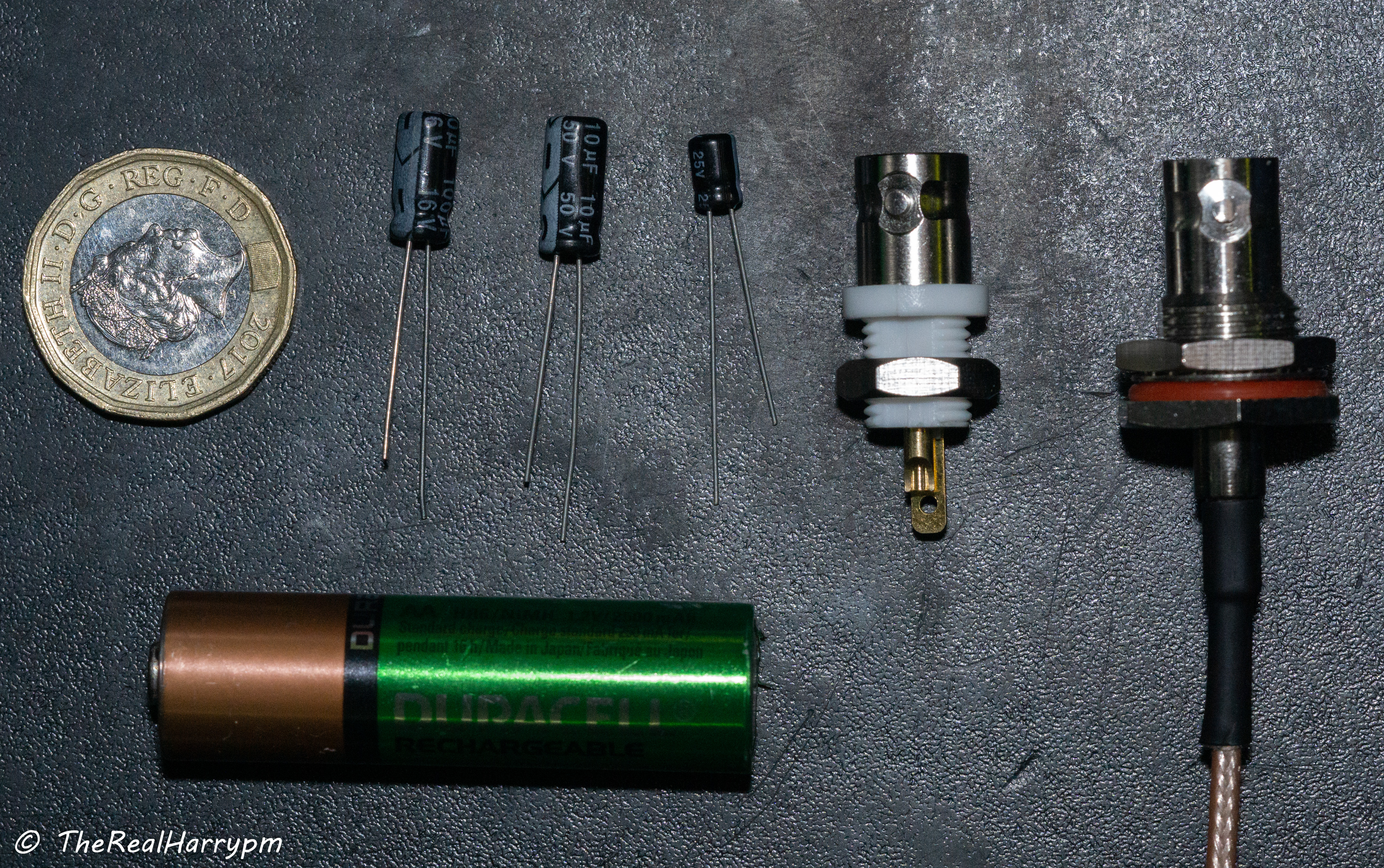 > £1 (GBP) Coin & AA Battery (size reference)
> [!NOTE]
> White CX Cards if you're not using the C31 mod, or adding a BNC, use a S-Video breakout the Y or Luma pin for the RF input.
## Connection Cables
- [Direct BNC to BNC](https://s.click.aliexpress.com/e/_DElVRiR)
- [50Ohm BNC to BNC Cable](https://s.click.aliexpress.com/e/_DlPgX4L)
- [S-Video to BNC](https://s.click.aliexpress.com/e/_DmR3gZv)
## DuPont Cables
- [DuPont Female to BNC](https://s.click.aliexpress.com/e/_Dldvh6B)
- [DuPont Male to BNC](https://s.click.aliexpress.com/e/_Dm1Bz6X)
- [SMA to DuPont Female](https://s.click.aliexpress.com/e/_DcZc8Dh)
## FPC Jigs (Sony Camcorders)
- [20pin Flex Cable](https://s.click.aliexpress.com/e/_DlANCwL)
- [20pin Jig (Unpopulated)](https://s.click.aliexpress.com/e/_DDO1CgX)
- [20pin Jig (With 2.54mm pins)](https://s.click.aliexpress.com/e/_DdmbTMT)
## Decode Projects Hardware
- [ADA4857 Amplifier](https://ko-fi.com/s/757bc4adbd)
- [CX Card Jigs for Clockgen Mod](https://ko-fi.com/s/a96ce9c656)
## Notes
- Having a 3rd arm holder with at least 2 metal clips is very helpful to hold connectors and the cable steady while soldering.
- The PINCEL/TS101 etc. can run off USB-C PD or DC (5 V–24 V) power and tips can be hot-swapped on the fly.
- Basic soldering iron kits generally come with basic tacky flux, a cleaning sponge, 2 ESD tweezers and a roll of 240 °C melting-point lead-free solder.
- The in-line capacitor method is generally a catch-all at the 10 uf mark. The 3.3 uf–100 uf range works fine, but 10 uf was standardised as it's widely available and has worked perfectly with many VHS/SVHS/Betamax/Video8/Hi8/Digital8 units.
## Cleaning Supplies
This is all you need for cleaning the head drum & VCR tracks boards and plastics even a light servicing can make a world of difference in reliability of a VCR.
- 99.9% IPA (Isopropanol/Rubbing alcohol) (Don't use on rubbers)
- Wet Wipes & Paper Towels (General Cleaning)
- Small dry Nail Wipes (Cleaning of VCR head/tracks/guides)
- Printer paper (Cleaning of VCR Heads)
- Cotton Buds (Q-Tips)
For initial board cleaning and removal of dust and other surface contaminants also recommended is:
- WD40 Electronics Cleaner (Aerosol Liquid Version of WD40 basically)
- [Assortment of Brushes](https://s.click.aliexpress.com/e/_DBe0bzD)
## Maintenance Supplies
- [Super Lube® Multi-Purpose Synthetic Grease](https://uk.rs-online.com/web/p/greases/1847967) (PTFE) (Tape Guides, Cogs) (Loctite 399420)
- Sewing machine oil (Metal bearings)
# Step 00: Inspect & Clean Your Device
> [!TIP]
> For Betamax/EIAJ players, using only alcohol-wetted paper is recommended for head cleaning as floating heads will catch easily on anything else, but chamois or lint-free microfibre works on VHS heads just fine.
- Always inspect & clean a VCR before running a tape. This is the best first action: not only so you don't contaminate or break your tapes, but also to protect the deck itself. If it's in good working order and has already been serviced, just clean the heads.
- Always remove the little head cleaner off the side of the drum if there is one, as they are just dirt spreaders and can cause contamination.
- Check that tape guide tracks are well lubricated if it looks shiny/bare then there's probably not enough.
- Pinch-roller bearings can be lubricated with a drop of oil, and guides can be cleaned with wipes; then use 99.9% isopropanol.
- Once cleaning has finished double check, if there are signal issues always good to check if there is cracked solder joints on the head drum from transport.
---
### Plastic back units
These can be marked and then poked through and slowly reamed into a round hole via a soldering iron at 340 °C. Be careful not to overdo it, and cut the excess off with cutters for a flush mounting of your connector; this is the easiest mod and looks very clean if you mark it properly.
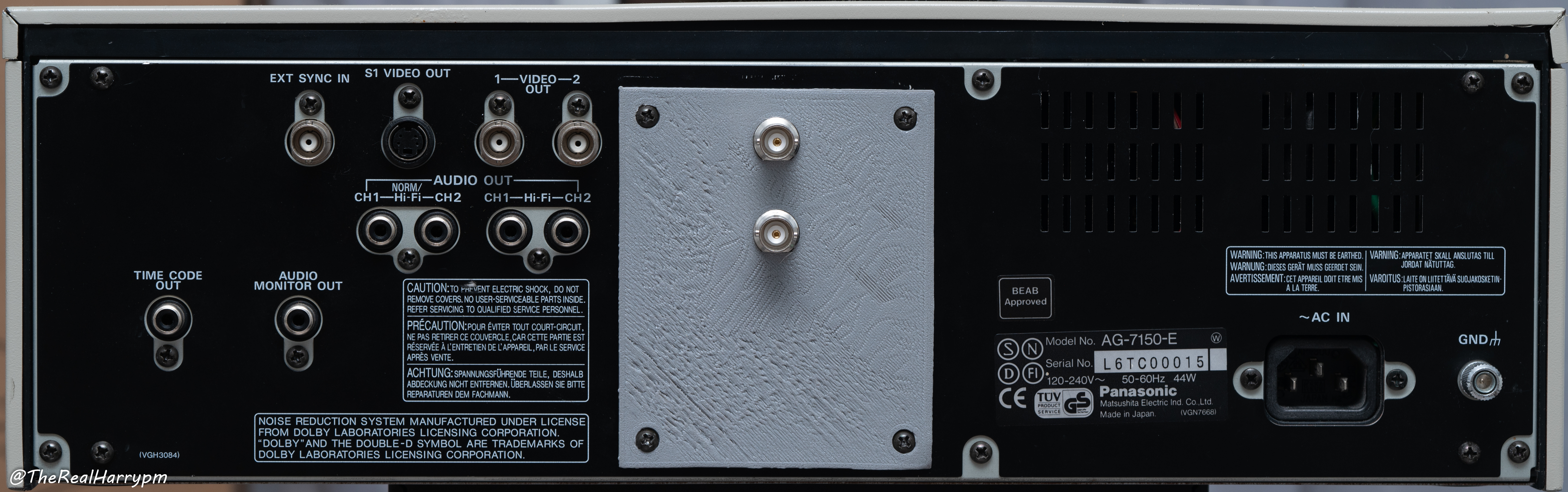
### Metal Units
These may require a 1/2-inch, or [stepping drill bit](https://s.click.aliexpress.com/e/_oDYg5Lt) ideal for bigger premade bulkhead cables. This is useful on decks like the MD/AG/BR lines of SVHS decks which normally have blank or user-replaceable add-in module panels for external deck control boards.
## Camcorders
Video8/Hi8/Digital8 Camcorders
- Find Test jig port at the back by the battery. (Should be a single JIS screw.)
- The tape loading door should be easily removed with 2 screws, allowing you to get inside to clean the head drum with chamois sticks and the overall area and tape path with brushes.
## Full Size Decks
- Firstly before you start doing anything, check the model number on the top/back/bottom label use this to find the service manual for your device via the wiki, if not then Google/Yahoo/DuckDuckGo is a good bet.
- Disconnect power, press power button and wait a few seconds to discharge your deck.
- Undo the 4 side securing screws
- Lifting upwards at an angle remove the lid/top panel and be careful around the edges.
> [!CAUTION]
> On metal ones, stamped metal sheets can cut through skin if you run a finger across the edge carelessly, but the lid should slide off upwards from the back of most standard VCR units.
----------
# Step 01: Find FM RF Test Points
> [!TIP]
> Video8, Hi8, BetaMax NTSC, and Laserdisc are always a single test point for Video & HiFi audio.
> £1 (GBP) Coin & AA Battery (size reference)
> [!NOTE]
> White CX Cards if you're not using the C31 mod, or adding a BNC, use a S-Video breakout the Y or Luma pin for the RF input.
## Connection Cables
- [Direct BNC to BNC](https://s.click.aliexpress.com/e/_DElVRiR)
- [50Ohm BNC to BNC Cable](https://s.click.aliexpress.com/e/_DlPgX4L)
- [S-Video to BNC](https://s.click.aliexpress.com/e/_DmR3gZv)
## DuPont Cables
- [DuPont Female to BNC](https://s.click.aliexpress.com/e/_Dldvh6B)
- [DuPont Male to BNC](https://s.click.aliexpress.com/e/_Dm1Bz6X)
- [SMA to DuPont Female](https://s.click.aliexpress.com/e/_DcZc8Dh)
## FPC Jigs (Sony Camcorders)
- [20pin Flex Cable](https://s.click.aliexpress.com/e/_DlANCwL)
- [20pin Jig (Unpopulated)](https://s.click.aliexpress.com/e/_DDO1CgX)
- [20pin Jig (With 2.54mm pins)](https://s.click.aliexpress.com/e/_DdmbTMT)
## Decode Projects Hardware
- [ADA4857 Amplifier](https://ko-fi.com/s/757bc4adbd)
- [CX Card Jigs for Clockgen Mod](https://ko-fi.com/s/a96ce9c656)
## Notes
- Having a 3rd arm holder with at least 2 metal clips is very helpful to hold connectors and the cable steady while soldering.
- The PINCEL/TS101 etc. can run off USB-C PD or DC (5 V–24 V) power and tips can be hot-swapped on the fly.
- Basic soldering iron kits generally come with basic tacky flux, a cleaning sponge, 2 ESD tweezers and a roll of 240 °C melting-point lead-free solder.
- The in-line capacitor method is generally a catch-all at the 10 uf mark. The 3.3 uf–100 uf range works fine, but 10 uf was standardised as it's widely available and has worked perfectly with many VHS/SVHS/Betamax/Video8/Hi8/Digital8 units.
## Cleaning Supplies
This is all you need for cleaning the head drum & VCR tracks boards and plastics even a light servicing can make a world of difference in reliability of a VCR.
- 99.9% IPA (Isopropanol/Rubbing alcohol) (Don't use on rubbers)
- Wet Wipes & Paper Towels (General Cleaning)
- Small dry Nail Wipes (Cleaning of VCR head/tracks/guides)
- Printer paper (Cleaning of VCR Heads)
- Cotton Buds (Q-Tips)
For initial board cleaning and removal of dust and other surface contaminants also recommended is:
- WD40 Electronics Cleaner (Aerosol Liquid Version of WD40 basically)
- [Assortment of Brushes](https://s.click.aliexpress.com/e/_DBe0bzD)
## Maintenance Supplies
- [Super Lube® Multi-Purpose Synthetic Grease](https://uk.rs-online.com/web/p/greases/1847967) (PTFE) (Tape Guides, Cogs) (Loctite 399420)
- Sewing machine oil (Metal bearings)
# Step 00: Inspect & Clean Your Device
> [!TIP]
> For Betamax/EIAJ players, using only alcohol-wetted paper is recommended for head cleaning as floating heads will catch easily on anything else, but chamois or lint-free microfibre works on VHS heads just fine.
- Always inspect & clean a VCR before running a tape. This is the best first action: not only so you don't contaminate or break your tapes, but also to protect the deck itself. If it's in good working order and has already been serviced, just clean the heads.
- Always remove the little head cleaner off the side of the drum if there is one, as they are just dirt spreaders and can cause contamination.
- Check that tape guide tracks are well lubricated if it looks shiny/bare then there's probably not enough.
- Pinch-roller bearings can be lubricated with a drop of oil, and guides can be cleaned with wipes; then use 99.9% isopropanol.
- Once cleaning has finished double check, if there are signal issues always good to check if there is cracked solder joints on the head drum from transport.
---
### Plastic back units
These can be marked and then poked through and slowly reamed into a round hole via a soldering iron at 340 °C. Be careful not to overdo it, and cut the excess off with cutters for a flush mounting of your connector; this is the easiest mod and looks very clean if you mark it properly.
### Metal Units
These may require a 1/2-inch, or [stepping drill bit](https://s.click.aliexpress.com/e/_oDYg5Lt) ideal for bigger premade bulkhead cables. This is useful on decks like the MD/AG/BR lines of SVHS decks which normally have blank or user-replaceable add-in module panels for external deck control boards.
## Camcorders
Video8/Hi8/Digital8 Camcorders
- Find Test jig port at the back by the battery. (Should be a single JIS screw.)
- The tape loading door should be easily removed with 2 screws, allowing you to get inside to clean the head drum with chamois sticks and the overall area and tape path with brushes.
## Full Size Decks
- Firstly before you start doing anything, check the model number on the top/back/bottom label use this to find the service manual for your device via the wiki, if not then Google/Yahoo/DuckDuckGo is a good bet.
- Disconnect power, press power button and wait a few seconds to discharge your deck.
- Undo the 4 side securing screws
- Lifting upwards at an angle remove the lid/top panel and be careful around the edges.
> [!CAUTION]
> On metal ones, stamped metal sheets can cut through skin if you run a finger across the edge carelessly, but the lid should slide off upwards from the back of most standard VCR units.
----------
# Step 01: Find FM RF Test Points
> [!TIP]
> Video8, Hi8, BetaMax NTSC, and Laserdisc are always a single test point for Video & HiFi audio.
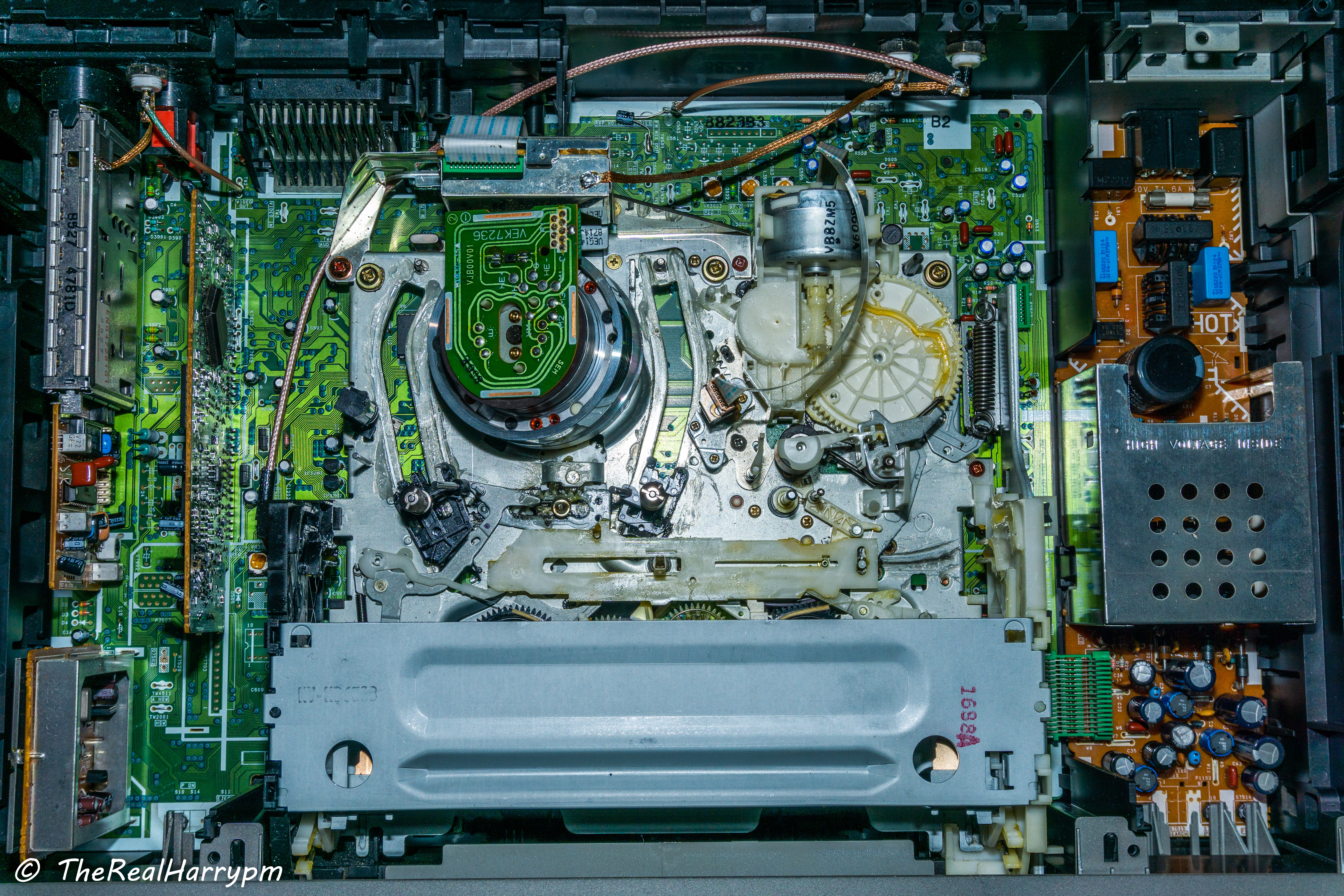
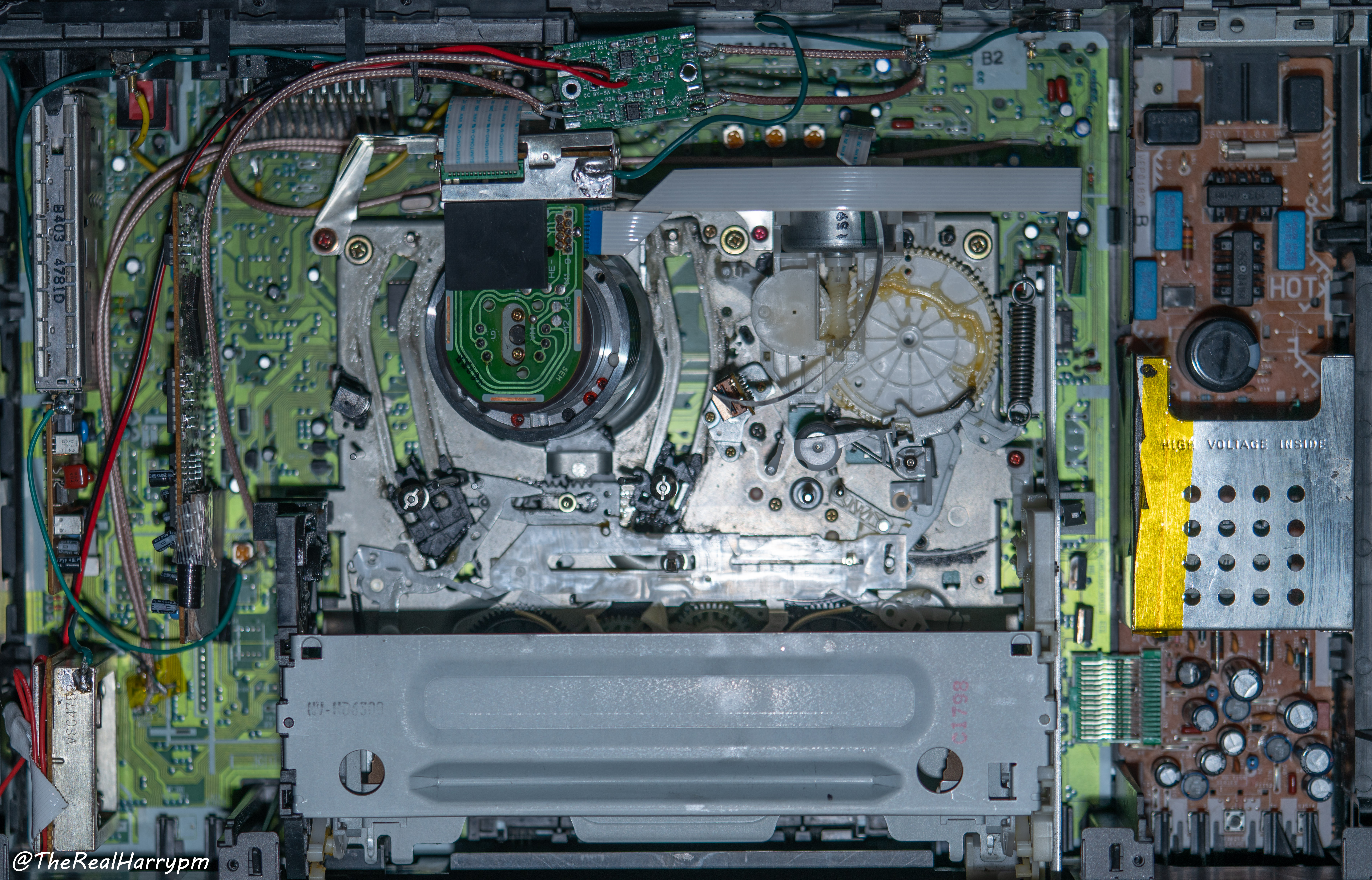
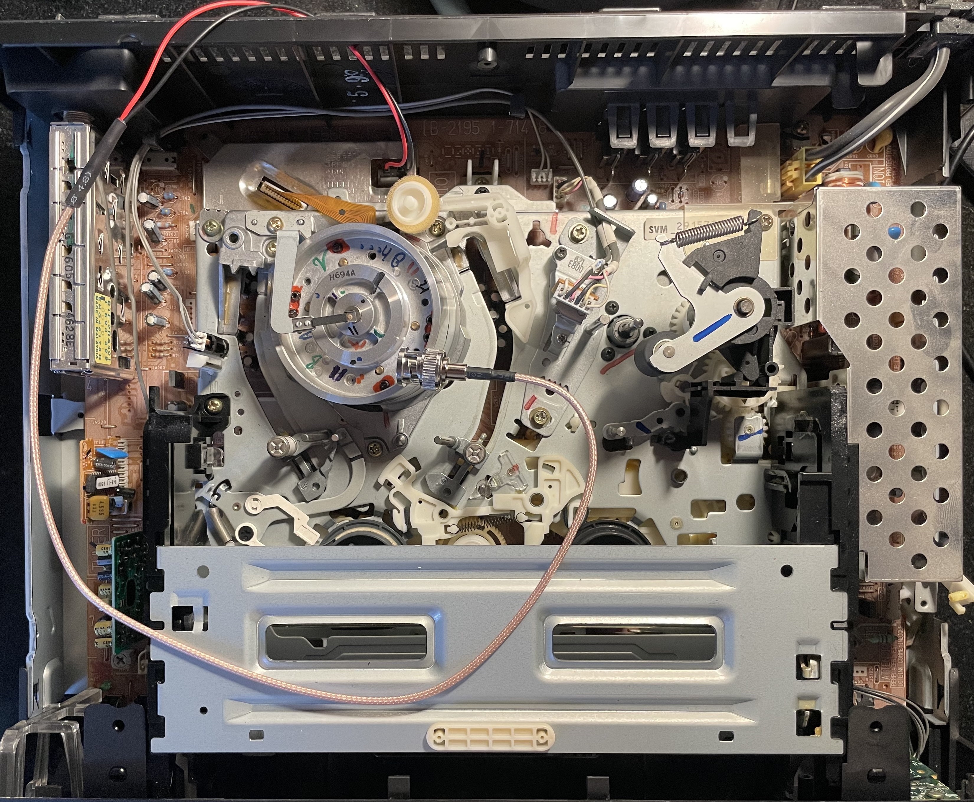
Visual colour Atlas of VHS VCR Hardware
This varies based on the year and market of the VCR. Modern later decks use more multi-role ICs, whereas prosumer to rackmount units will have core parts for each processing task on dedicated boards and be mostly through-hole parts.
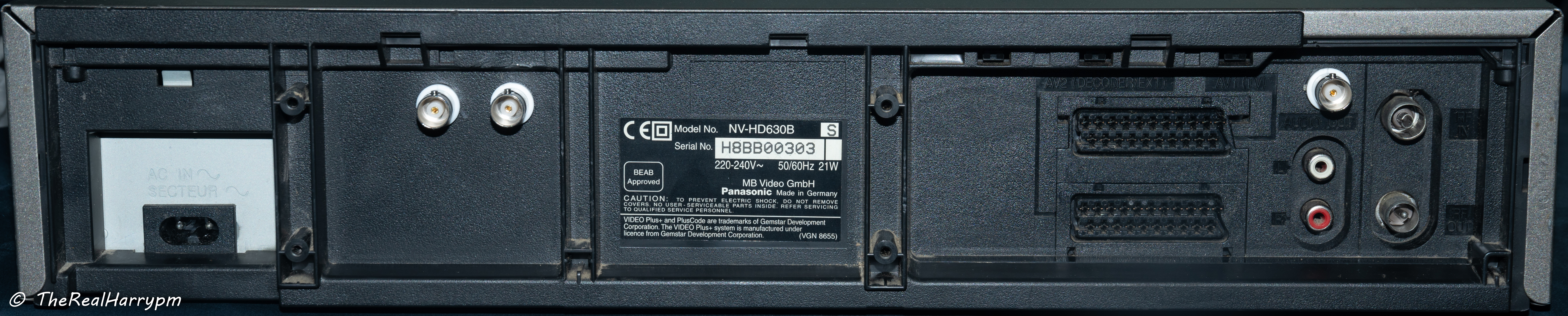
Panasonic NV-HD630 For Example
 > [!CAUTION]
> - Be careful to not touch the mains AC power supply area with both hands this can shock you and or kill you if you bridge the AC stage but generally, these have metal shielding and are isolated off to one side of the VCR.
> - Always service equipment after it has been un-plugged and discharged of power.
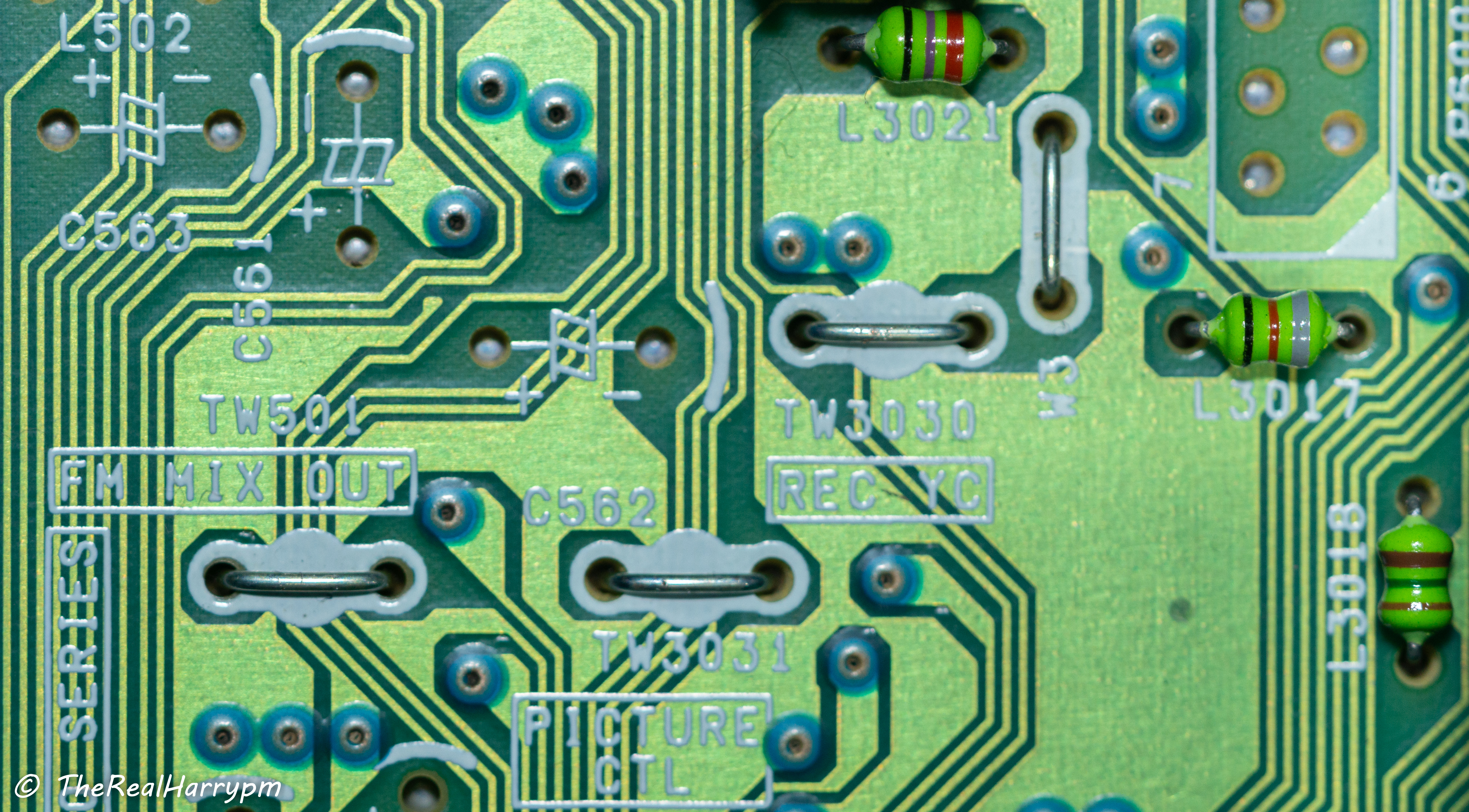
Numbered Boxes In RED test point locations for signals.
1. TW3001 RF C - Video FM
2. TW501 FM Mix Out - HiFi FM RF
3. TW26 CVBS Out - Composite Video Output
4. TW3 CVBS Input - Composite Video Input
5. TW502 - ENVE (HiFi FM RF)
Left-hand Side
- Pink - TV Modulation & De-modulation pack
- Golden Yellow - Audio Processing (Nicam)
- Bright Yellow - Video Processing
Middle
- Purple - Head Amplifier Board
- Blue Box - VCR Loading & Playback Mechanical System or "Mech"
- Yellow Circle - VCR Head Drum & Connection Board
- Green Circle - Tape Guides & Guide Path
- Light Blue Left - Erase Head
- Orange Circle - Linear Audio or Edge Track Audio Heads
- Light Blue Right - Rubber Pinch Roller
- Brown Boxes Centre/Right - Head Drum RF Ribbon
Right-hand Side
- Red - AC Power Supply Stage
- Green - DC Power Supply Stage
> [!CAUTION]
> - Be careful to not touch the mains AC power supply area with both hands this can shock you and or kill you if you bridge the AC stage but generally, these have metal shielding and are isolated off to one side of the VCR.
> - Always service equipment after it has been un-plugged and discharged of power.
Numbered Boxes In RED test point locations for signals.
1. TW3001 RF C - Video FM
2. TW501 FM Mix Out - HiFi FM RF
3. TW26 CVBS Out - Composite Video Output
4. TW3 CVBS Input - Composite Video Input
5. TW502 - ENVE (HiFi FM RF)
Left-hand Side
- Pink - TV Modulation & De-modulation pack
- Golden Yellow - Audio Processing (Nicam)
- Bright Yellow - Video Processing
Middle
- Purple - Head Amplifier Board
- Blue Box - VCR Loading & Playback Mechanical System or "Mech"
- Yellow Circle - VCR Head Drum & Connection Board
- Green Circle - Tape Guides & Guide Path
- Light Blue Left - Erase Head
- Orange Circle - Linear Audio or Edge Track Audio Heads
- Light Blue Right - Rubber Pinch Roller
- Brown Boxes Centre/Right - Head Drum RF Ribbon
Right-hand Side
- Red - AC Power Supply Stage
- Green - DC Power Supply Stage
1. Note the model number
2. Find the service manual
3. Locate your test points in manual
4. Locate your test points visually
Video FM RF / HiFi FM RF / Headswitch / Linear Audio
This list is a work in progress based on service manuals and direct user experiences and may not include every possible name but covers the majority of VCR's PCB board & service manual wording wise.
> [!NOTE]
> Most decks will also have a composite test point which can be useful for adding a composite output/input on SCART-only decks.
> [!NOTE]
> If your VCR was serviced likely there are some pen marks on the board at test point locations.
## Test Point Names
These are the relative names, you may also want to look for `chroma amp` and `audio amp` when tracing paths from a IC chip.
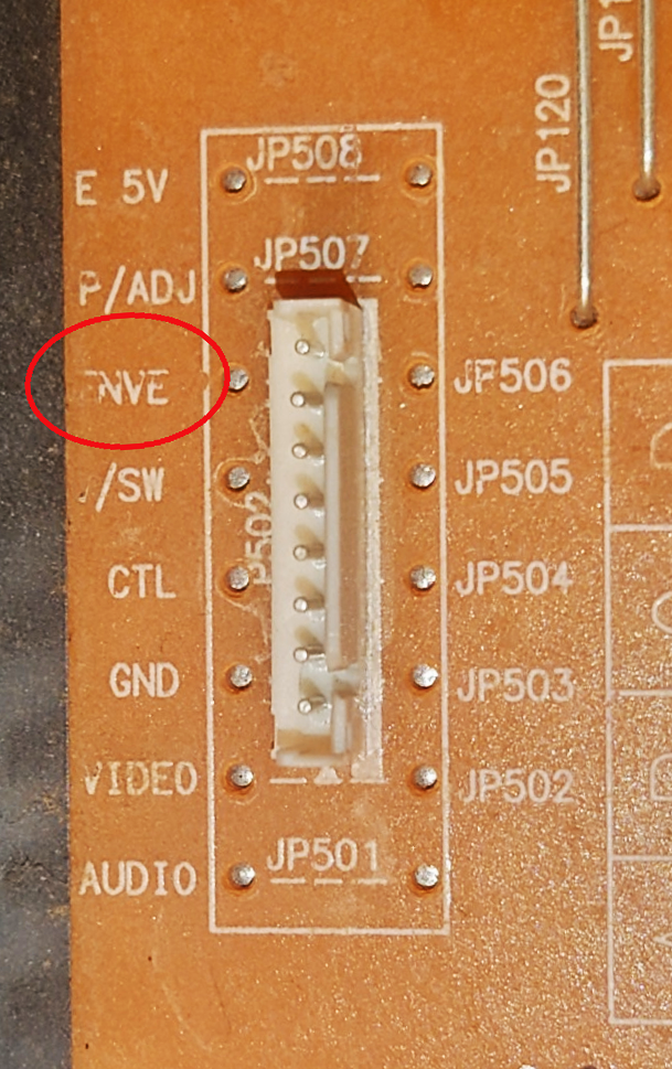
**Video FM RF Signal:**
`RF C`, `RF Y`, `RF Y+C`, `V RF`, `PB`, `PB.FM`, `V ENV`, `ENV`, `ENVE`, `ENVELOPE`, `VIDEO ENVE`, `VIDEO ENVELOPE`
> [!IMPORTANT]
> "ENVELOPE" in various forms can also sometimes refer to a voltage level signal derived from the FM signal used for auto-tracking so it's important to check with the service manual.
**HiFi Audio FM Signal:**
`HiFi`, `A.PB`, `A FM`, `A.PB.FM`, `Audio FM`, `A ENV`, `AENV`, `HIFI Envelope`, `FM Mix Out`
**Linear Baseband Signal**
`A-Out`, `A. Out`
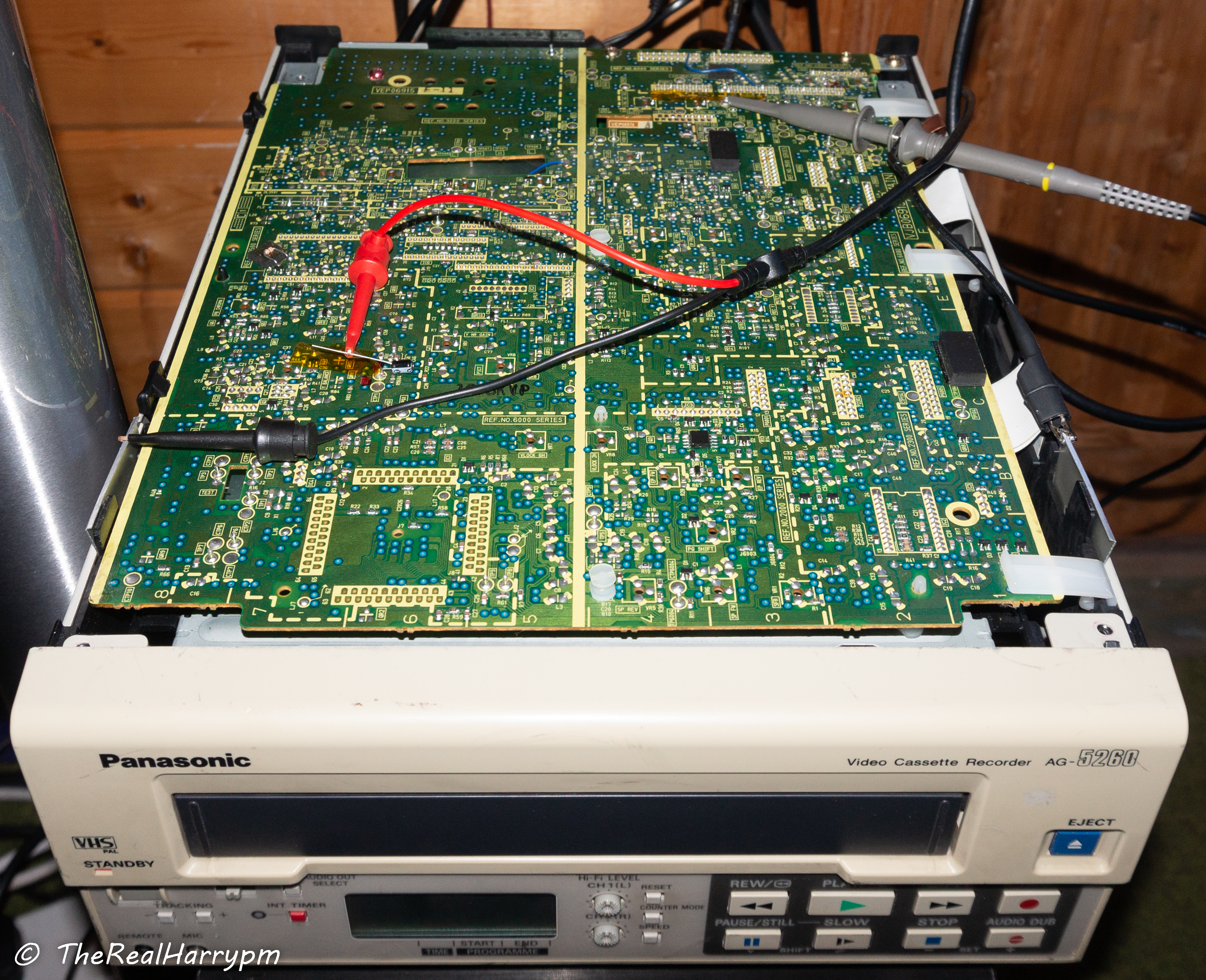
## How to read service manuals
> [!TIP]
> Right Click --> Open Image in New Tab
**Follow the yellow brick road (The Contrasting Line Indicators)**
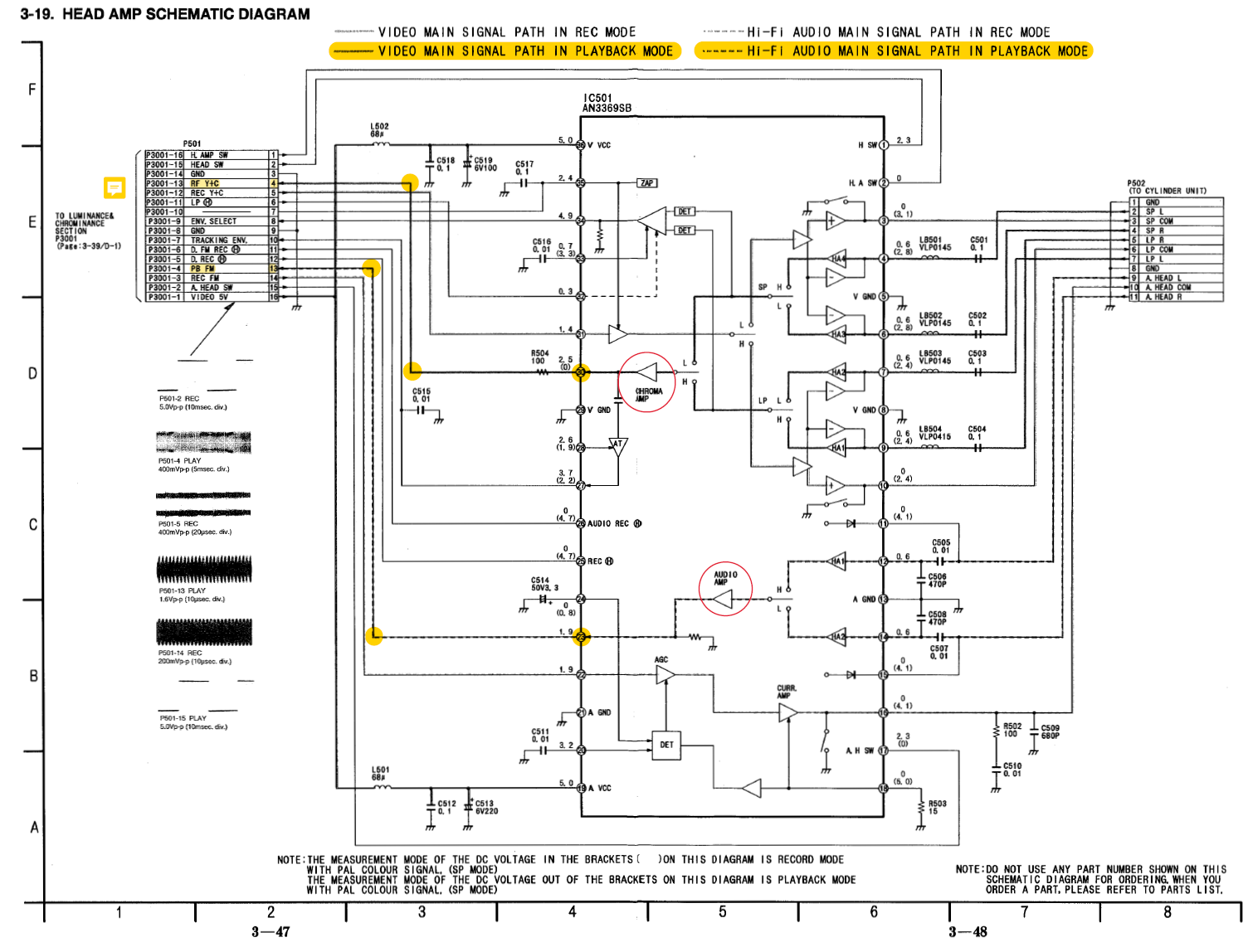 In modern manuals the servicing book will directly correspond to labels physically on the boards in older manuals, they will look like TW1000 but be TW1 on the boards label or silkscreen for example.
For good example, HiFi on the AG-7150 is TP4707 in the manual it just says 707 on the label, it's sometimes confusing if you're not used to reading them or probing every test point, even then some test points for HiFi may be filtered like they are on AG decks requiring you to tap from the head amplifier board directly.
There is always contrasting arrows showing the signal path on service manual diagrams, trace the line to find test points along the signal path.
`Heads --> Pre-amplification --> Test Points --> Video Processing --> Baseband Video Playback`
> [!NOTE]
> Sometimes both test points can be called ENV.
## Types of Test Points
Test points vary in type generally all are through-hole, but SMD pad style is also a thing.
Consumer Decks will have bar style and floating bar style test points with floating being easy to probe but bar style generally needs fine tip probes.
Prosumer & Professional decks typically have hook-to and poll-style easy test points to solder to and are easily user accessible.
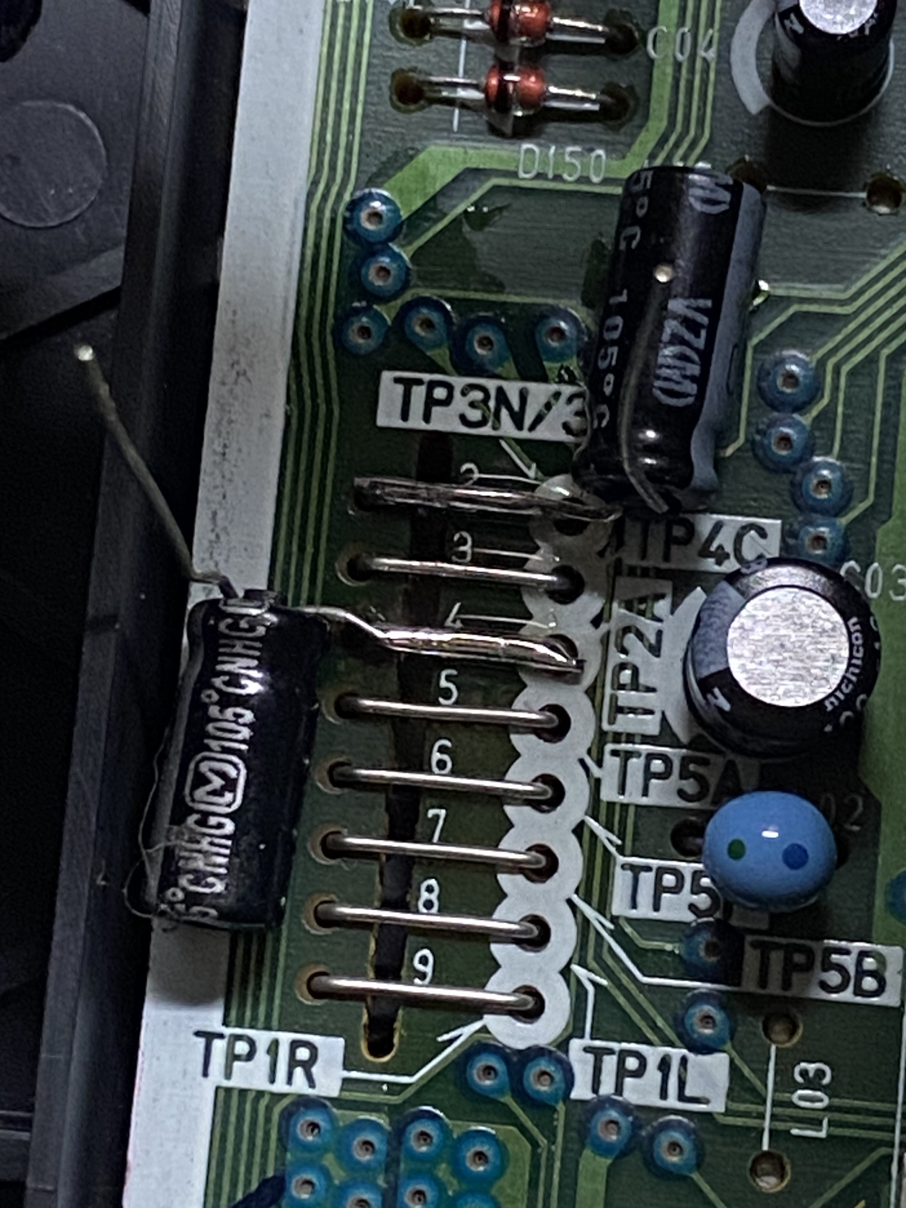
Most Sony-made Decks from VHS to Betamax will have 2.54mm headers for DuPont Connector or breakout jig use. Newer Daewoo-made VCRs also used pin headers originally meant to hook up a jig board.
Some Video8 & Hi8 devices have service jig points via universal flex cables.
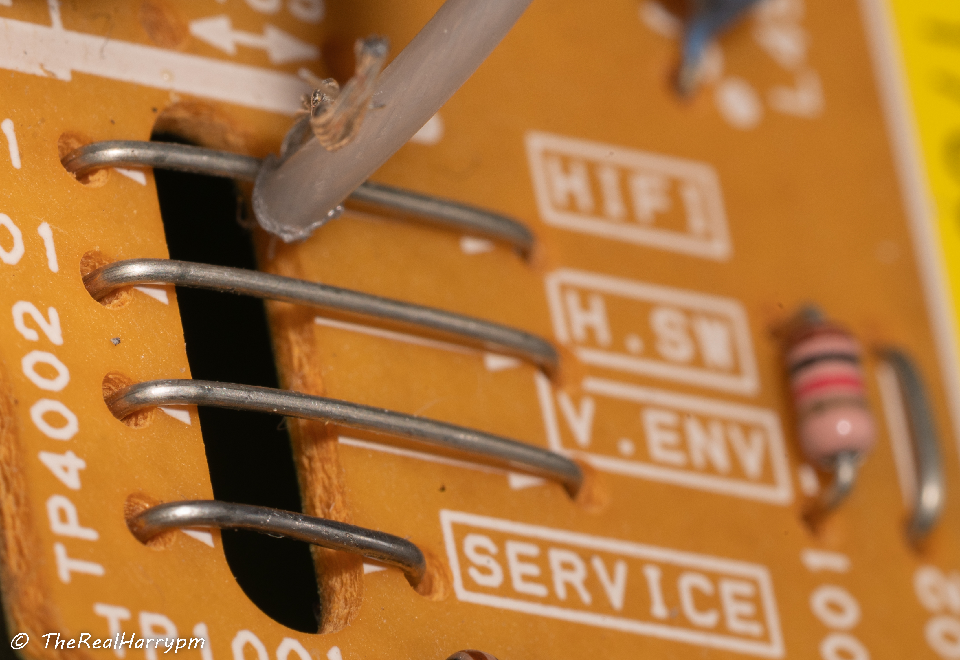
### Flat Bar Style
In modern manuals the servicing book will directly correspond to labels physically on the boards in older manuals, they will look like TW1000 but be TW1 on the boards label or silkscreen for example.
For good example, HiFi on the AG-7150 is TP4707 in the manual it just says 707 on the label, it's sometimes confusing if you're not used to reading them or probing every test point, even then some test points for HiFi may be filtered like they are on AG decks requiring you to tap from the head amplifier board directly.
There is always contrasting arrows showing the signal path on service manual diagrams, trace the line to find test points along the signal path.
`Heads --> Pre-amplification --> Test Points --> Video Processing --> Baseband Video Playback`
> [!NOTE]
> Sometimes both test points can be called ENV.
## Types of Test Points
Test points vary in type generally all are through-hole, but SMD pad style is also a thing.
Consumer Decks will have bar style and floating bar style test points with floating being easy to probe but bar style generally needs fine tip probes.
Prosumer & Professional decks typically have hook-to and poll-style easy test points to solder to and are easily user accessible.
Most Sony-made Decks from VHS to Betamax will have 2.54mm headers for DuPont Connector or breakout jig use. Newer Daewoo-made VCRs also used pin headers originally meant to hook up a jig board.
Some Video8 & Hi8 devices have service jig points via universal flex cables.
### Flat Bar Style
 ### Floating Bar Style
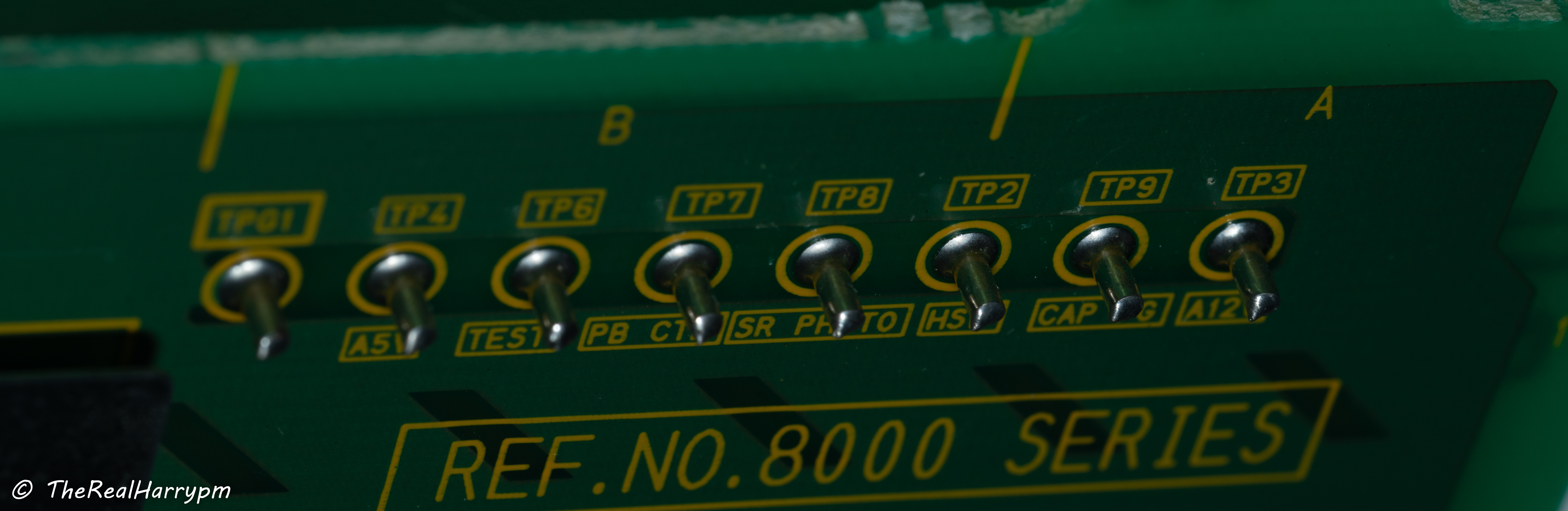
 ### Poll Style
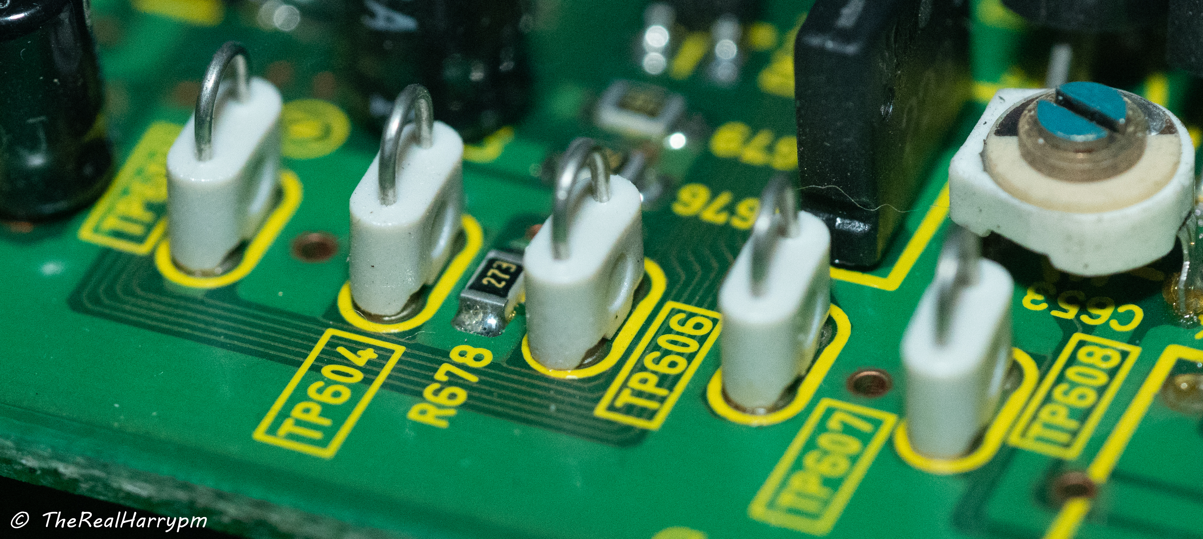
 ### Loop Style
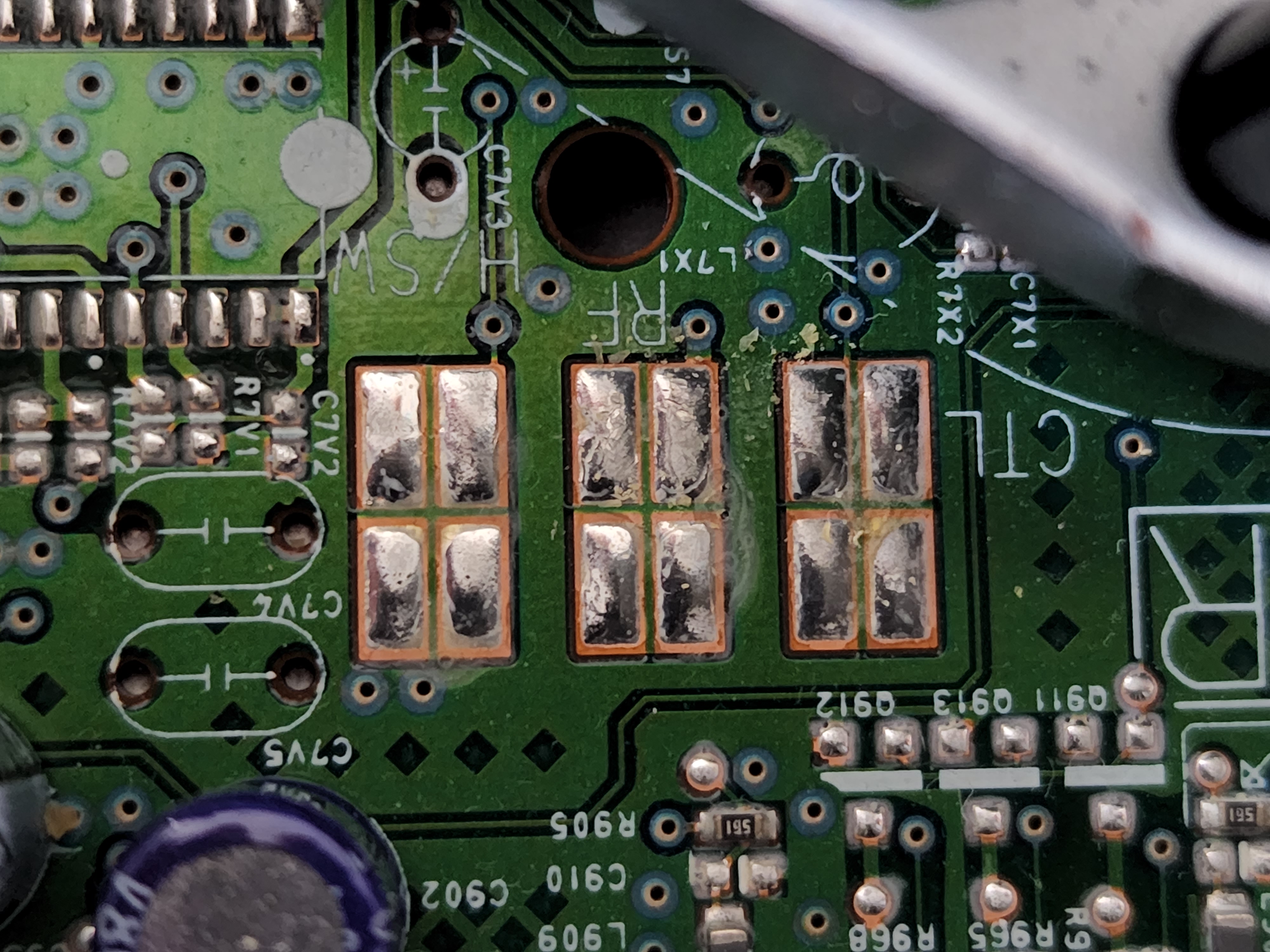
 ### Pad Style
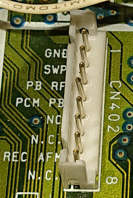
 ### Header Pin (2.54mm) "DuPont"
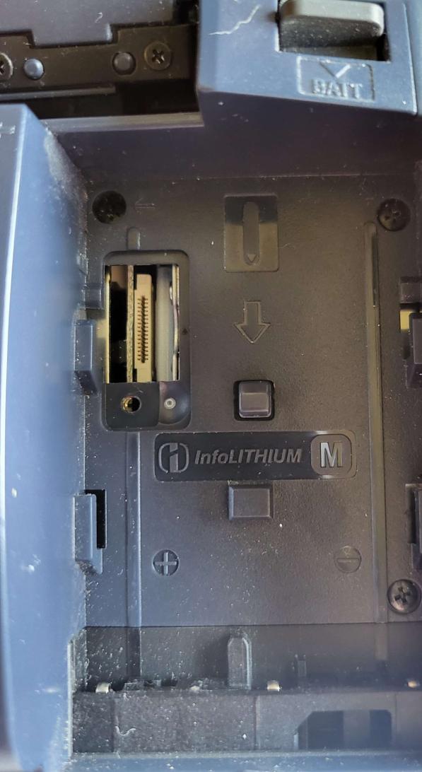
 ### Jig Port or 0.5mm FPC Flex Cable Connector
 ## Types of RF Connectors
## **BNC**
Is the best for fixed backports with a locking and reliable connector used in everything from 1960's communications gear to current-day cine cameras, this is the most preferred connector due to reliability.
Cable End Type
## Types of RF Connectors
## **BNC**
Is the best for fixed backports with a locking and reliable connector used in everything from 1960's communications gear to current-day cine cameras, this is the most preferred connector due to reliability.
Cable End Type
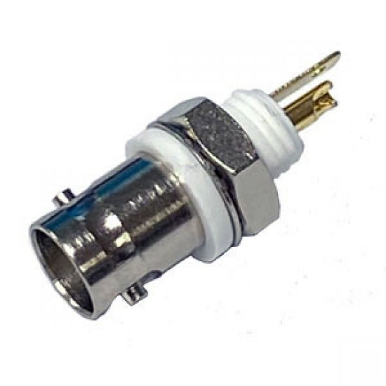
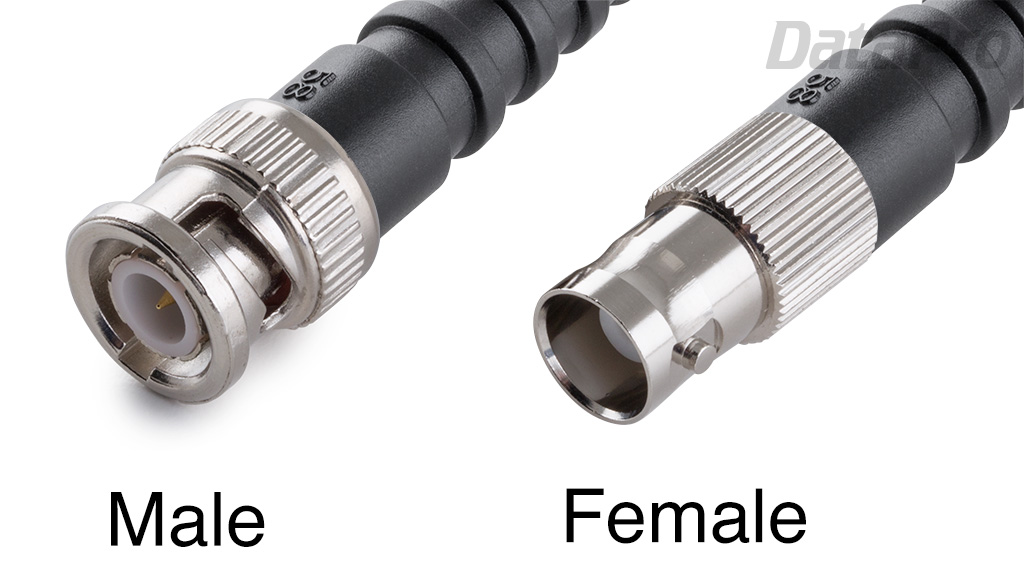 > [!NOTE]
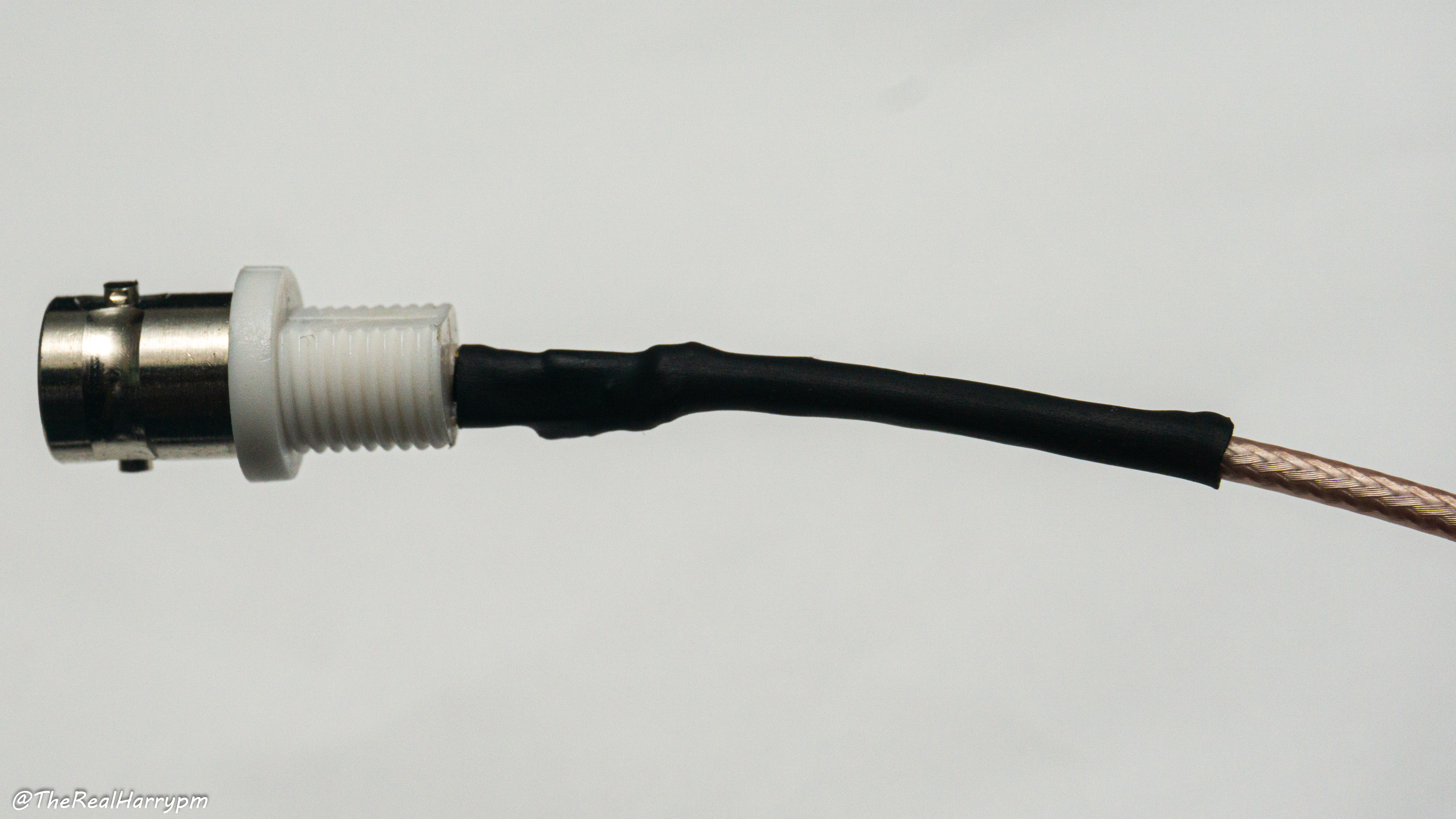
> There are 2 types of BNC metal with outer ground and plastic with isolated ground on a leg.
Bulkhead Small Solderable (Ideal for plastic decks)
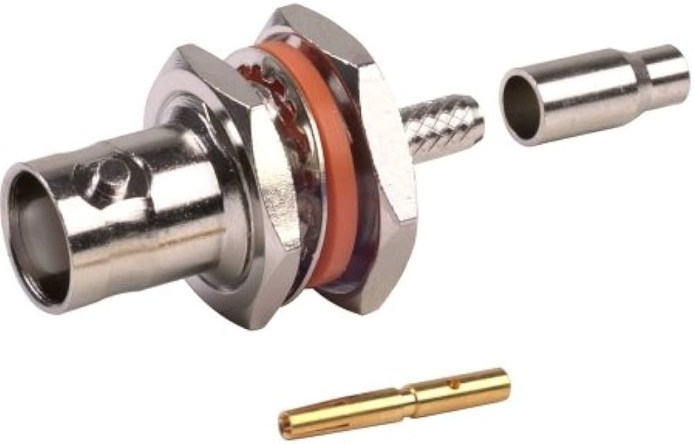
> [!NOTE]
> There are 2 types of BNC metal with outer ground and plastic with isolated ground on a leg.
Bulkhead Small Solderable (Ideal for plastic decks)
 Bulkhead Heavy Crimp (Standard for pre-crimped bulkhead cables)
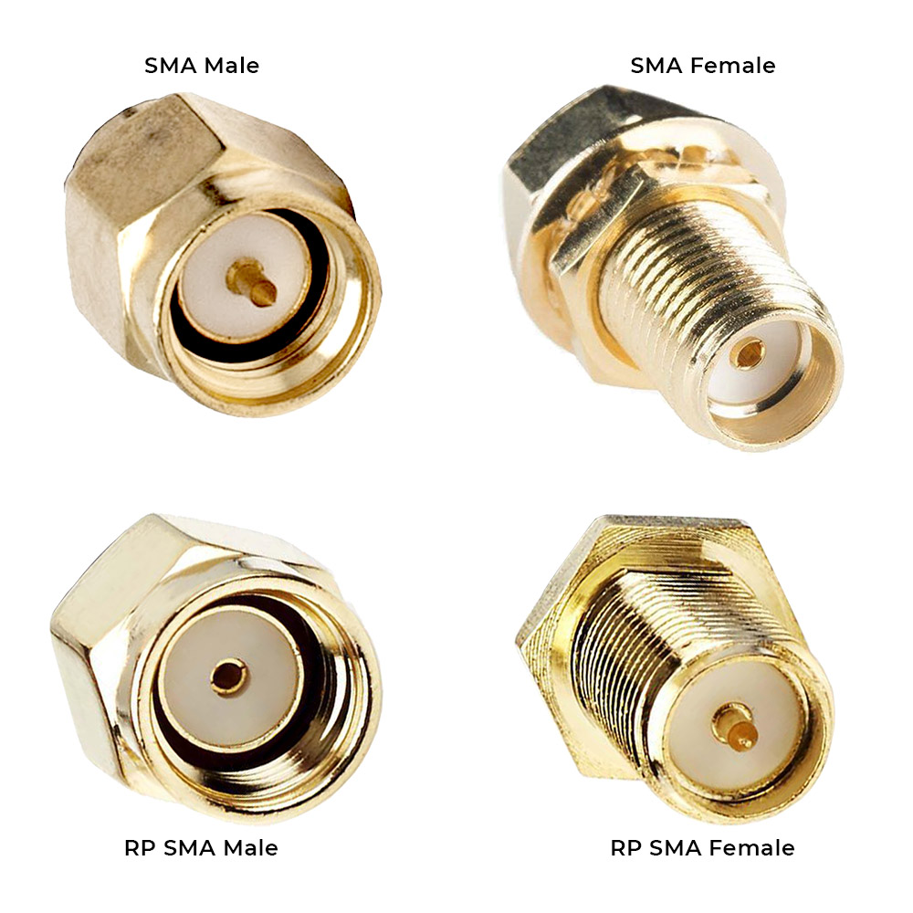
 ## **SMA**
Is a flat external-sided, threaded locking connector found on almost all common consumer RF devices such as 4G/5G, Wi-Fi Dongles, Handset radio units a small and versatile connector for internal use
> [!NOTE]
> SMA is not the most physically strong for external use, unlike BNC/TNC you will see on Yagi antennas and other such RF equipment.
> [!TIP]
> RP stands for reversed polarity, so the signal is on the ground and the ground is internal these pins are respectively also re-versed for these connectors.
## **SMA**
Is a flat external-sided, threaded locking connector found on almost all common consumer RF devices such as 4G/5G, Wi-Fi Dongles, Handset radio units a small and versatile connector for internal use
> [!NOTE]
> SMA is not the most physically strong for external use, unlike BNC/TNC you will see on Yagi antennas and other such RF equipment.
> [!TIP]
> RP stands for reversed polarity, so the signal is on the ground and the ground is internal these pins are respectively also re-versed for these connectors.
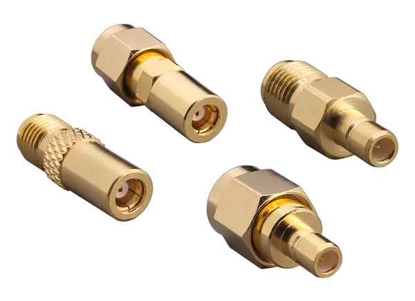
 ## **SMB**
Is the lesser-known sibling of SMA, but it's a tighter than TS-9 style non-locking connector.
## **SMB**
Is the lesser-known sibling of SMA, but it's a tighter than TS-9 style non-locking connector.
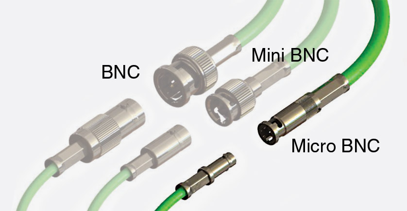
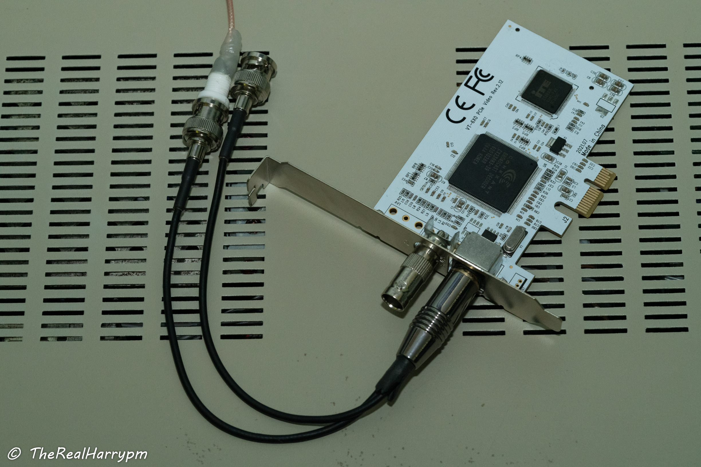
 ## **Micro-BNC**
Also called DIN 1.0/2.3 Is the smallest locking knock-safe connector seen on portable equipment like PCIe cards and field recorders (Reference Part Number: 45K201-400L5)
## **Micro-BNC**
Also called DIN 1.0/2.3 Is the smallest locking knock-safe connector seen on portable equipment like PCIe cards and field recorders (Reference Part Number: 45K201-400L5)
 ## DuPont Connector "Header Pins"
These are the most widely known connector, technically called a 2.54 mm header pin. These are used for kids' kits, diagnostic test points or low-power/data connectors for computer hardware such as fans or Molex power; these normally use 26 AWG wire.
## DuPont Connector "Header Pins"
These are the most widely known connector, technically called a 2.54 mm header pin. These are used for kids' kits, diagnostic test points or low-power/data connectors for computer hardware such as fans or Molex power; these normally use 26 AWG wire.
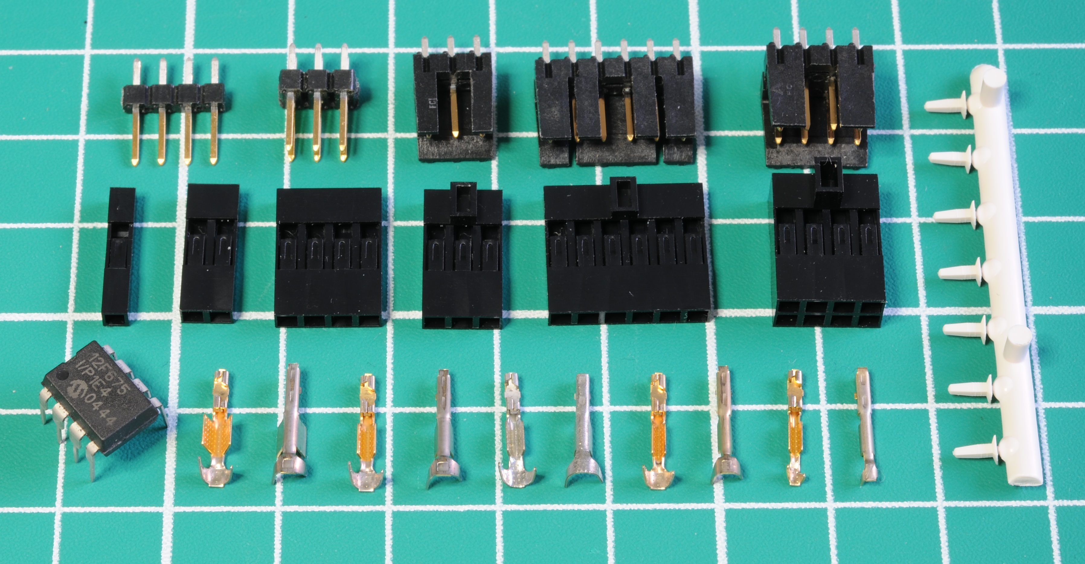 Credit to Matthew Millman for the image and wonderful guide on the history and crimping these types of connectors that can be found [here](https://www.mattmillman.com/info/crimpconnectors/dupont-and-dupont-connectors/).
## JST Connector
Shorthand for Japan Solderless Terminal, widely used on Japan based electronics and critically Laserdisc Players.
Credit to Matthew Millman for the image and wonderful guide on the history and crimping these types of connectors that can be found [here](https://www.mattmillman.com/info/crimpconnectors/dupont-and-dupont-connectors/).
## JST Connector
Shorthand for Japan Solderless Terminal, widely used on Japan based electronics and critically Laserdisc Players.
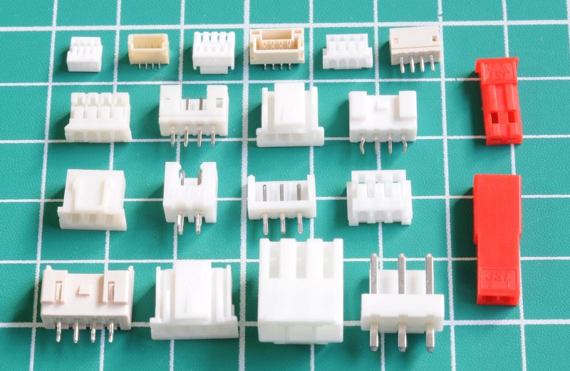 Credit to Matthew Millman for the image and wonderful guide on the history and crimping these types of connectors that can be found [here](https://www.mattmillman.com/info/crimpconnectors/common-jst-connector-types/).
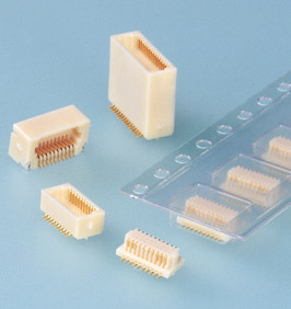
## JMC Connector
Semi obscure today but was widely used in the 1990s stacked electronics and for test points with "push in" jig modules, these are mostly found on Video8 camcorders.
- [You can see an index of part versions here](https://www.jst.com/products/automotive-connectors/jmc-connector/)
Credit to Matthew Millman for the image and wonderful guide on the history and crimping these types of connectors that can be found [here](https://www.mattmillman.com/info/crimpconnectors/common-jst-connector-types/).
## JMC Connector
Semi obscure today but was widely used in the 1990s stacked electronics and for test points with "push in" jig modules, these are mostly found on Video8 camcorders.
- [You can see an index of part versions here](https://www.jst.com/products/automotive-connectors/jmc-connector/)
 ## Header Pin "Jig Breakout Boards"
With FPC Flex ribbon Cables jig points are broken out to dedicated pins, on basic PCB boards.
## Header Pin "Jig Breakout Boards"
With FPC Flex ribbon Cables jig points are broken out to dedicated pins, on basic PCB boards.
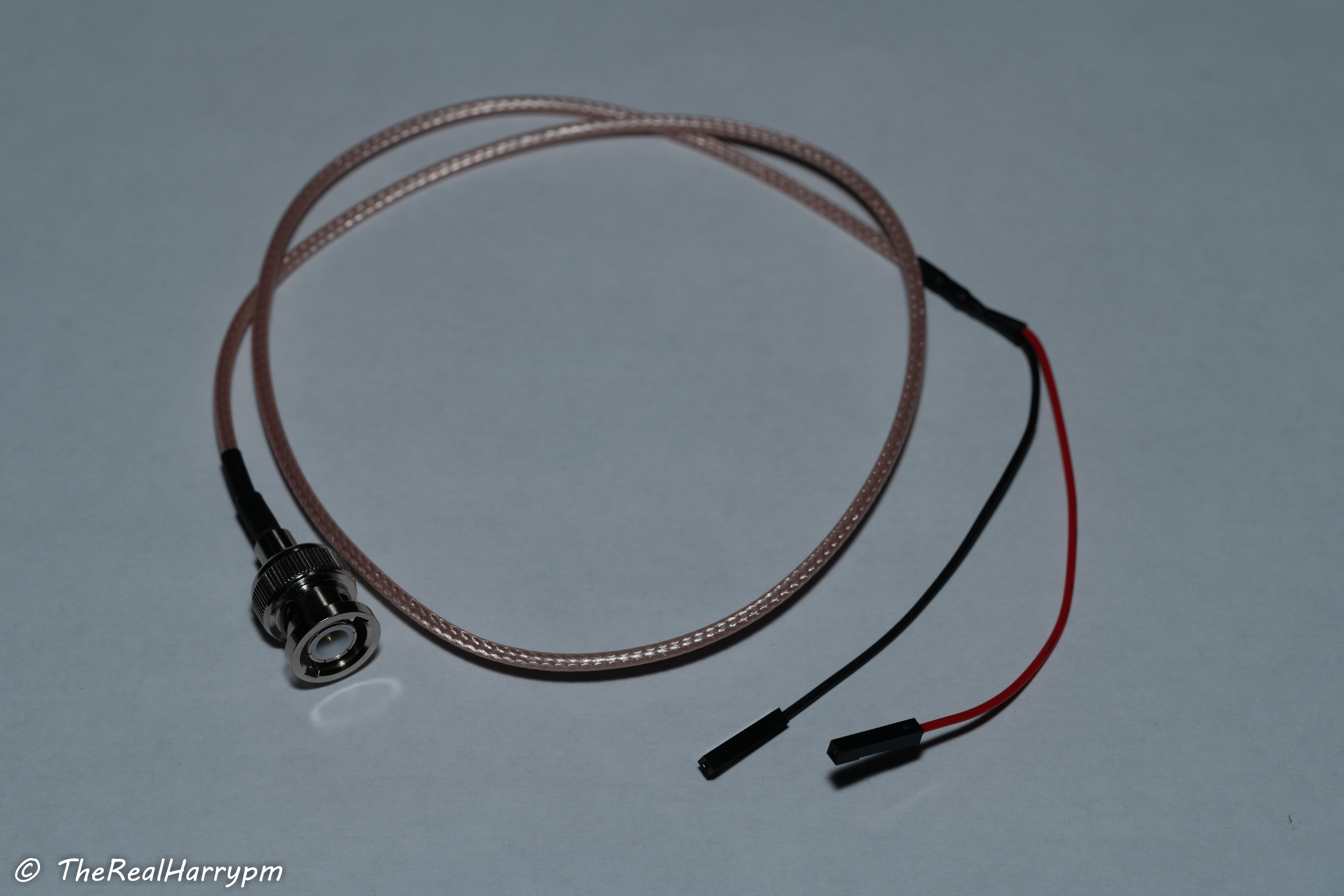
 ## DuPont Cables
If you wish to not hard modify players or a jig board then you can install a capacitor in-line or use a DC blocker this is very much so helpful with using test probes.
- BNC Male to DuPont Female cable.
## DuPont Cables
If you wish to not hard modify players or a jig board then you can install a capacitor in-line or use a DC blocker this is very much so helpful with using test probes.
- BNC Male to DuPont Female cable.
 - In-Line Splice method adding a ceramic in-line to the signal wire.
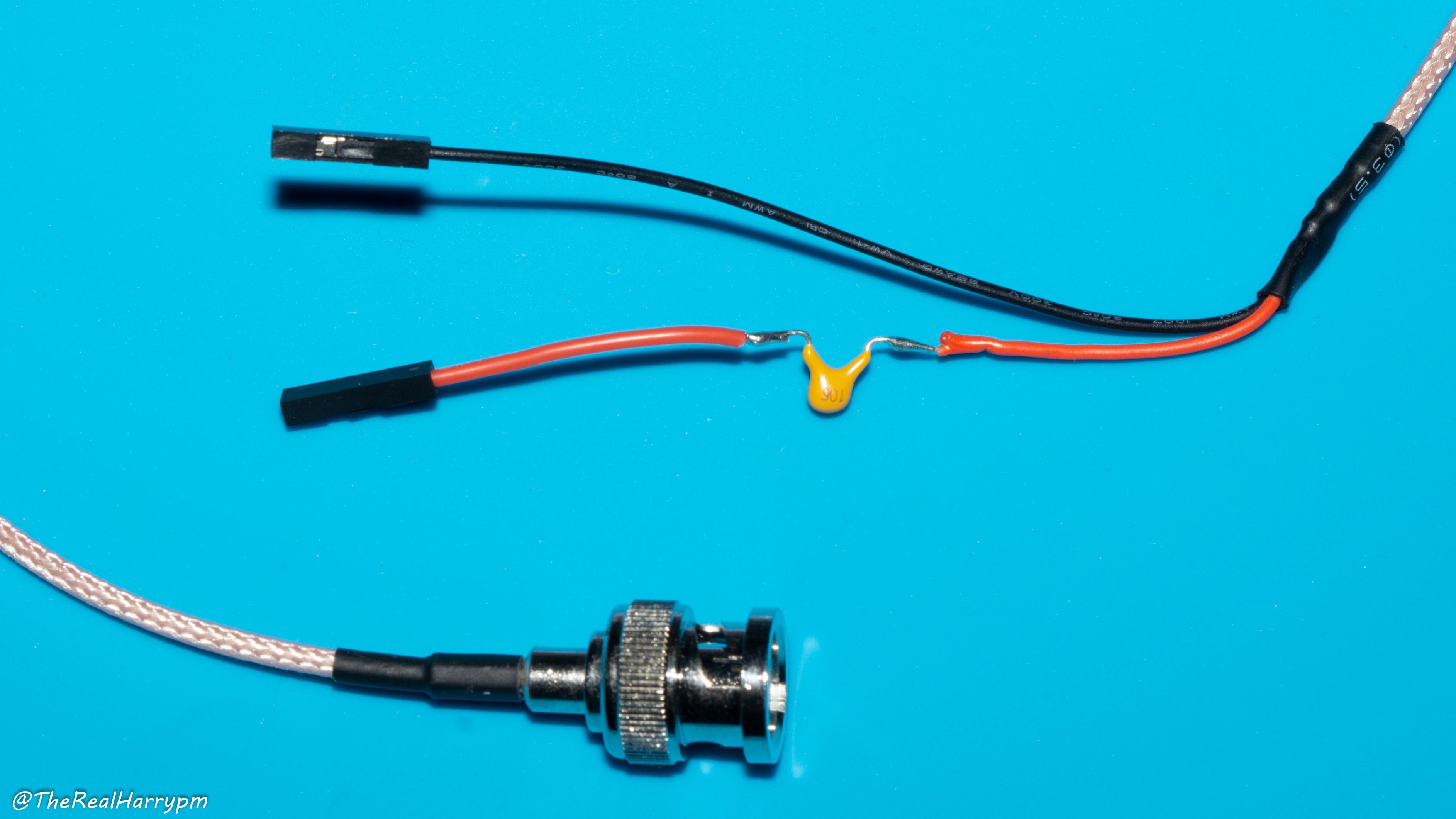 - BNC DC Blocker Adapter [AliExpress](https://s.click.aliexpress.com/e/_ombwZNl)
 # Step 02: Cabling & Planning
 - Pick your cable type, and decide on bulkhead type.
- `RG316` - Thicker used on most 50ohm premade cables
- `RG178` thinner and more flexible for internal use.
- Note both have practically the same performance in terms of RF signal at `50~100cm` of length, most taps are under `30cm`.
- Premade BNC bulkheads can be chopped and cut to size, allowing you to mount first and solder later once routing is planned.
# Step 03: Mounting & Routing
Metal decks will normally need a drill press, but plastics decks can be easily melted and excesses cut away.
> [!TIP]
> Conical tips can be used to melt all the way or just to make quick guide holes for drill bits, be sure to do this outside as the ABS plastics used is toxic and if inhaled heavy is very bad, can clean your tip quickly after doing so.
- Pick your cable type, and decide on bulkhead type.
- `RG316` - Thicker used on most 50ohm premade cables
- `RG178` thinner and more flexible for internal use.
- Note both have practically the same performance in terms of RF signal at `50~100cm` of length, most taps are under `30cm`.
- Premade BNC bulkheads can be chopped and cut to size, allowing you to mount first and solder later once routing is planned.
# Step 03: Mounting & Routing
Metal decks will normally need a drill press, but plastics decks can be easily melted and excesses cut away.
> [!TIP]
> Conical tips can be used to melt all the way or just to make quick guide holes for drill bits, be sure to do this outside as the ABS plastics used is toxic and if inhaled heavy is very bad, can clean your tip quickly after doing so.
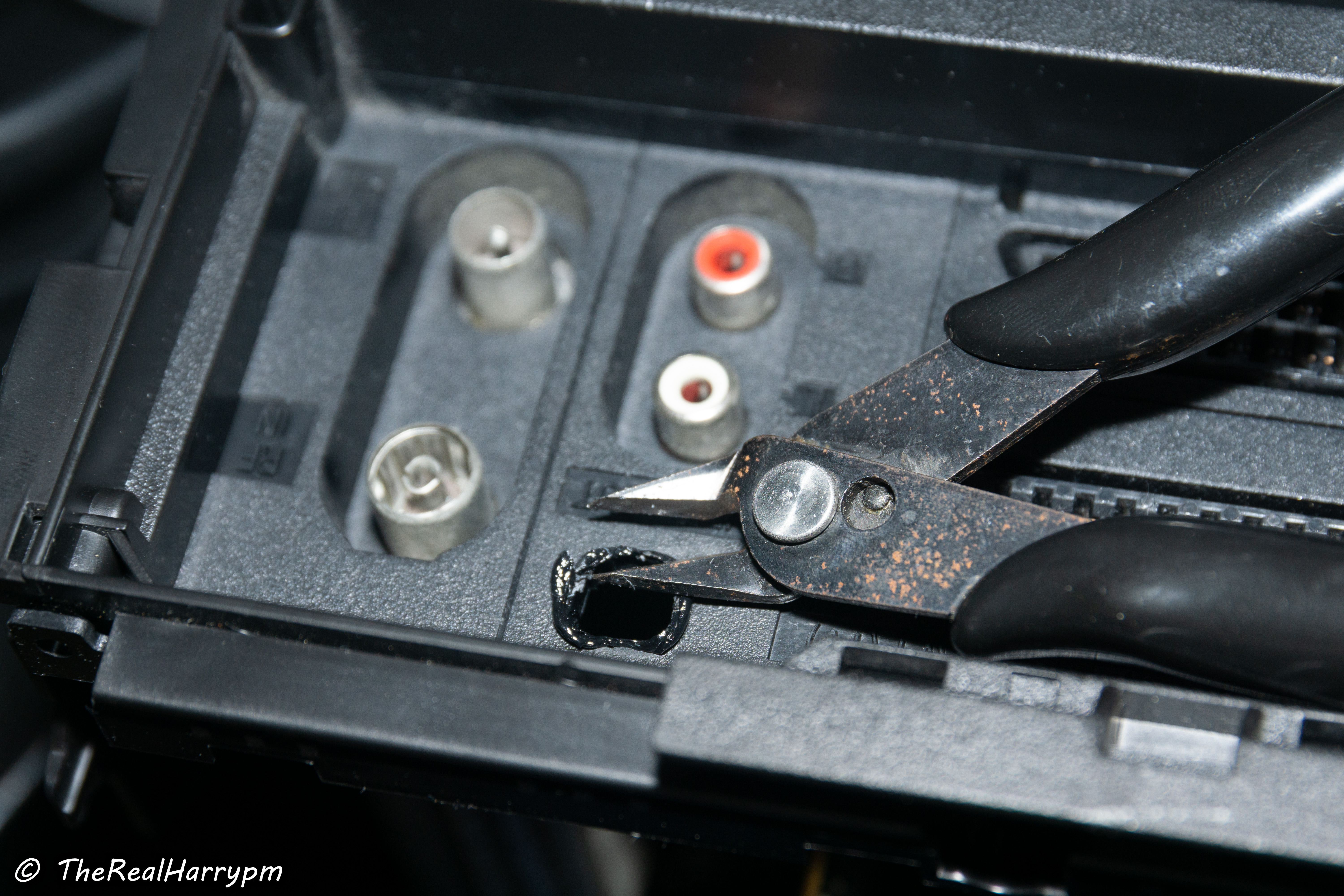 Cut away excess and flush mount your BNC connectors.
 After finding the best places for the BNC bulkheads and test fitting them you can then route your cable to the necessary length.
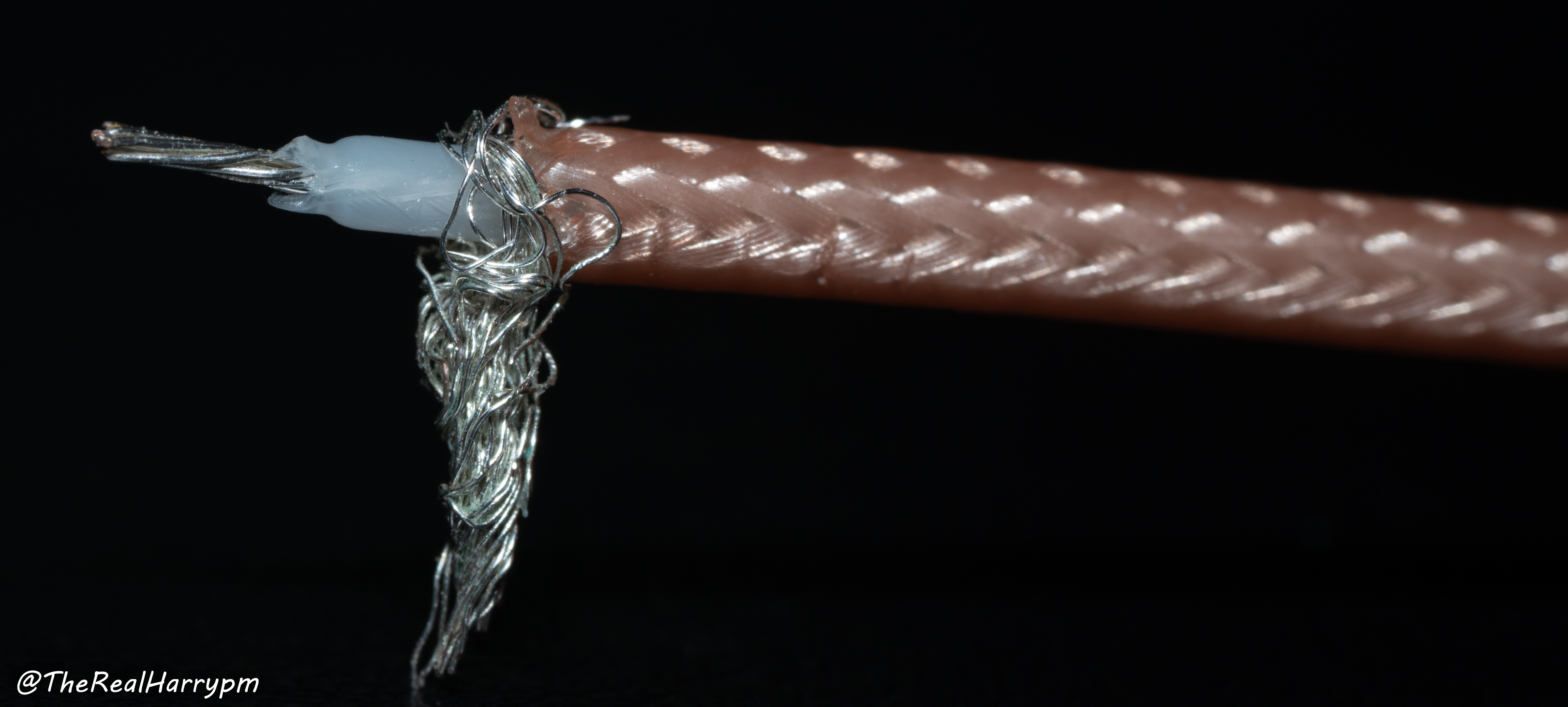
 # Step 04: Stripping & Soldering Cables
Keep these 3 things handy at this stage
- Cutters
- Automatic Wire Strippers
- Ruler
- Bevel Soldering Tip
Measure with 5-10cm of slack your cable run from your test point to where you would like to mount your BNC on your unit normally this is at the back and or next to the normal audio and video output ports.
1. Prepare your iron at `280-320°C` keep it tinned until ready for use, then clean apply new solder.
2. Measure about 3cm of cable length and mark it with a pen or your iron.
3. Strip your cable, using a pair of automatic wire strippers.
4. Pull back the outside strained wires and twist it together and tin the end with a little fresh solder.
5. Melt or strip the inner wire twist it together and tin the end with a little fresh solder.
You can also strip the inner via soldering iron at `320°C` the outer insulation layer will melt so you can rim around the outer cable then carefully pull it off with tweezers or fingers.
# Step 04: Stripping & Soldering Cables
Keep these 3 things handy at this stage
- Cutters
- Automatic Wire Strippers
- Ruler
- Bevel Soldering Tip
Measure with 5-10cm of slack your cable run from your test point to where you would like to mount your BNC on your unit normally this is at the back and or next to the normal audio and video output ports.
1. Prepare your iron at `280-320°C` keep it tinned until ready for use, then clean apply new solder.
2. Measure about 3cm of cable length and mark it with a pen or your iron.
3. Strip your cable, using a pair of automatic wire strippers.
4. Pull back the outside strained wires and twist it together and tin the end with a little fresh solder.
5. Melt or strip the inner wire twist it together and tin the end with a little fresh solder.
You can also strip the inner via soldering iron at `320°C` the outer insulation layer will melt so you can rim around the outer cable then carefully pull it off with tweezers or fingers.
 The inner insulator is easier to pressure the cable with the tip of your iron against a surface like ceramic in a pulling motion and you will easily strip the insulation off.
> [!TIP]
> Twist the inner wire strands and tap the end with a bit of solder, this stops the wire from fraying.
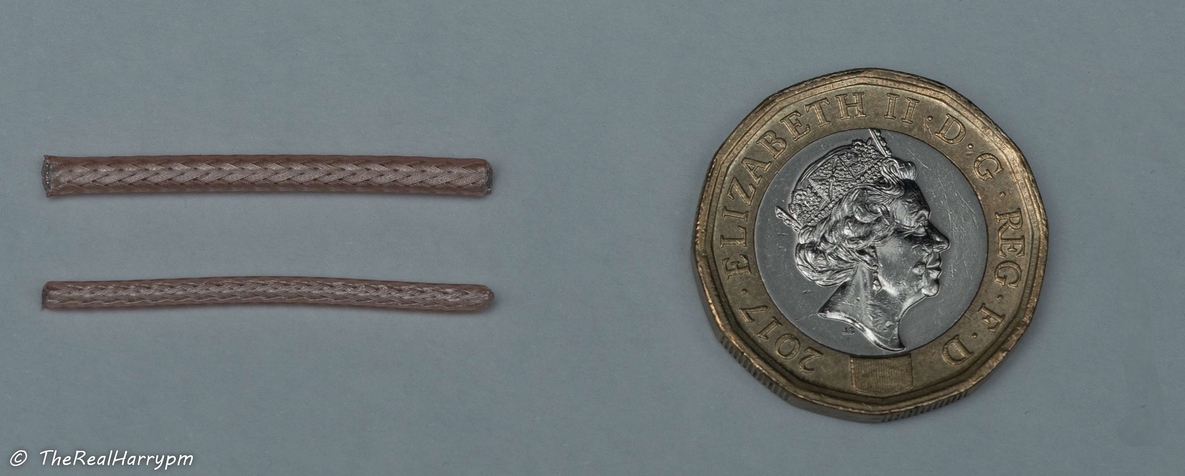
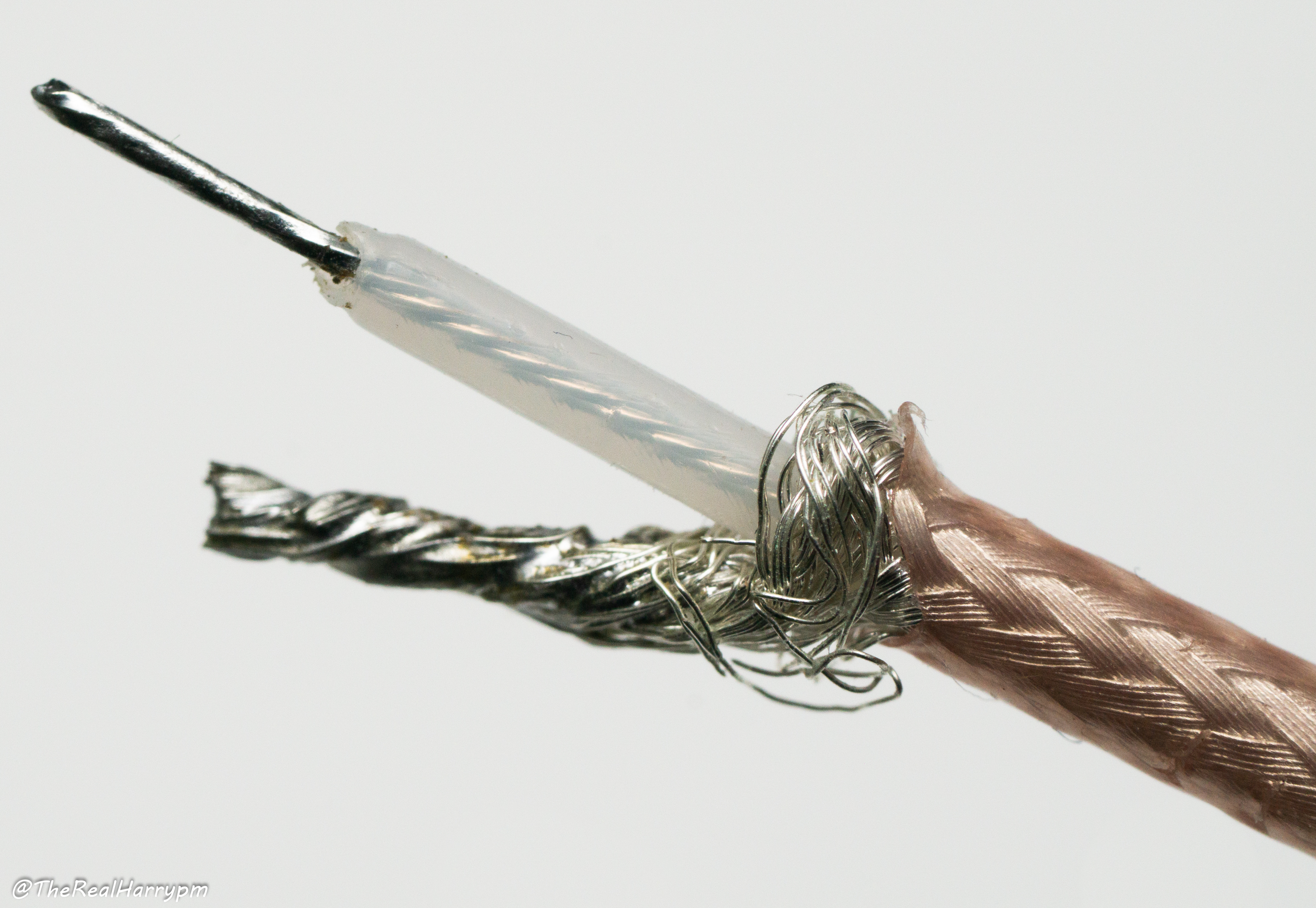
### Properly Stripped Cable
The inner insulator is easier to pressure the cable with the tip of your iron against a surface like ceramic in a pulling motion and you will easily strip the insulation off.
> [!TIP]
> Twist the inner wire strands and tap the end with a bit of solder, this stops the wire from fraying.
### Properly Stripped Cable
 > [!CAUTION]
> Without fluxing & tinning this wire you may have insulation residue, automatic wire strippers are more suited for this task but can be slightly tricky with RG316 on short pieces of wire.
### Properly Tinned Cable
Ends are finger twisted, then fresh solder is flowed onto them with a bevel/chisel tip.
> [!CAUTION]
> Without fluxing & tinning this wire you may have insulation residue, automatic wire strippers are more suited for this task but can be slightly tricky with RG316 on short pieces of wire.
### Properly Tinned Cable
Ends are finger twisted, then fresh solder is flowed onto them with a bevel/chisel tip.
 ### Then measure up to the BNC connector & solder it
> [!TIP]
> If a premade bulkhead is used you can solder the inner strained wire after tinning it to a capacitor and then solder the leg to the board which can be helpful as you can hold the capacitor with tweezers or a finger.
### Then measure up to the BNC connector & solder it
> [!TIP]
> If a premade bulkhead is used you can solder the inner strained wire after tinning it to a capacitor and then solder the leg to the board which can be helpful as you can hold the capacitor with tweezers or a finger.
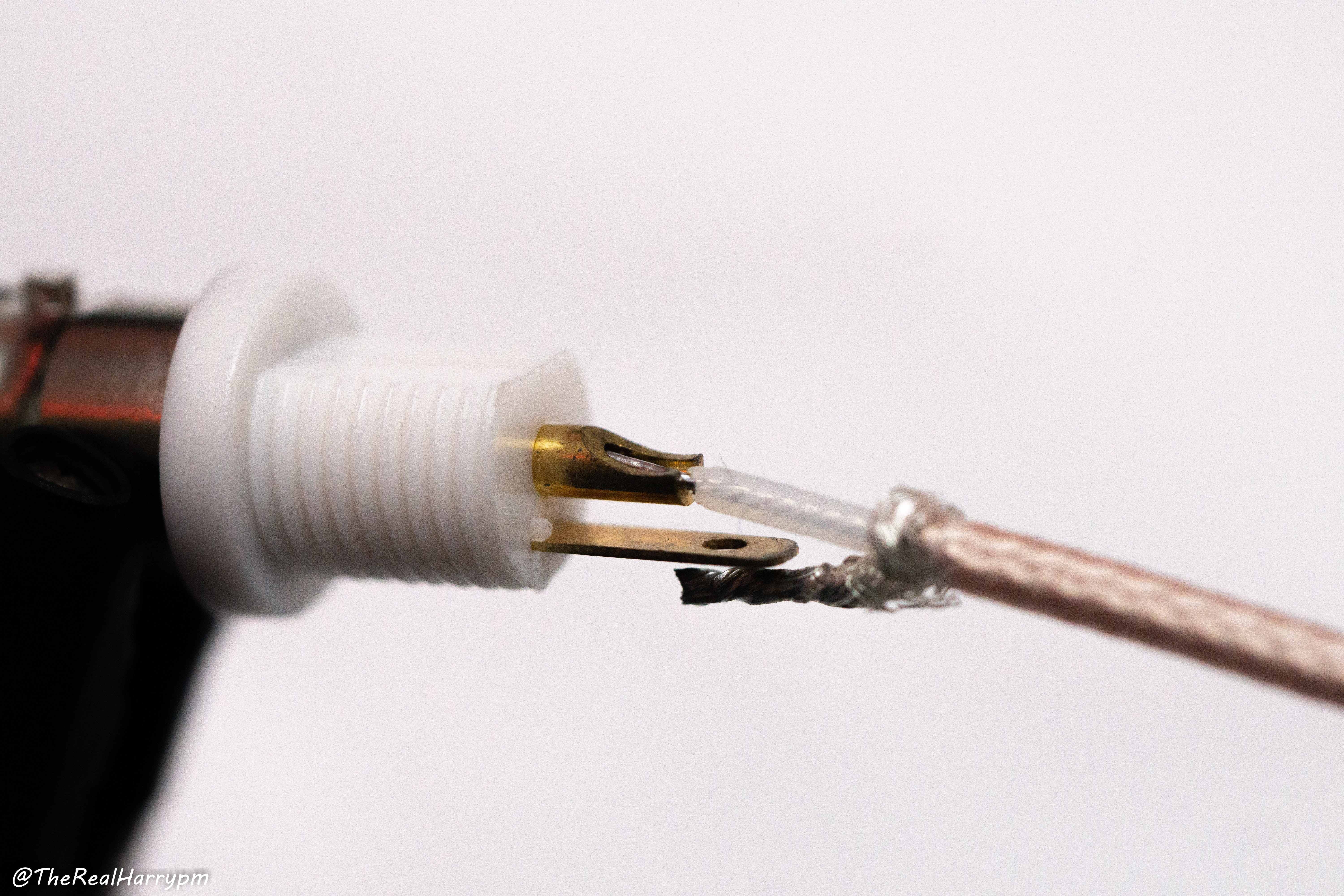 1. Use a bevel/flat tip (conical tips you can use but will be more fiddly)
2. Clean and flow a very small amount of fresh solder onto your Iron.
3. Add a small amount of flux into the centre pinhole, insert cable.
4. Holding the cable inside the connectors, then while pressing the pin gently with your iron push and flow solder into the open end of the connector until filled, but not overflowing.
5. Wipe excess flux off, after RF capture tests you can insulate this connector.
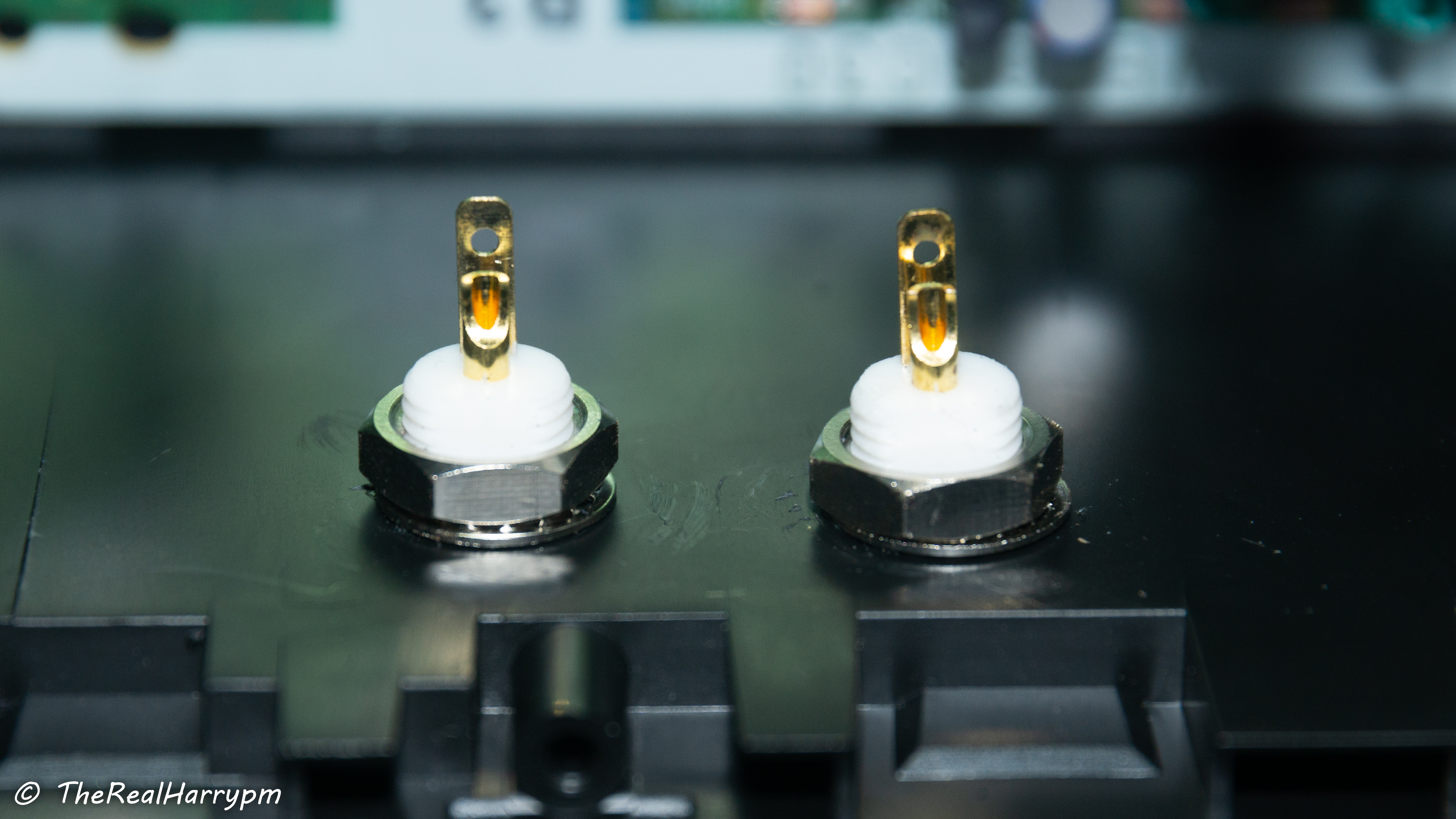
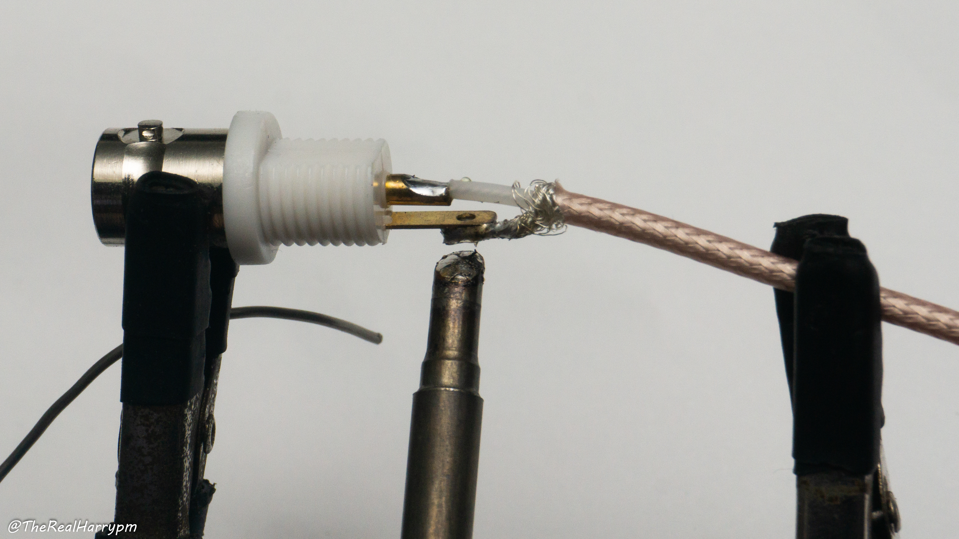
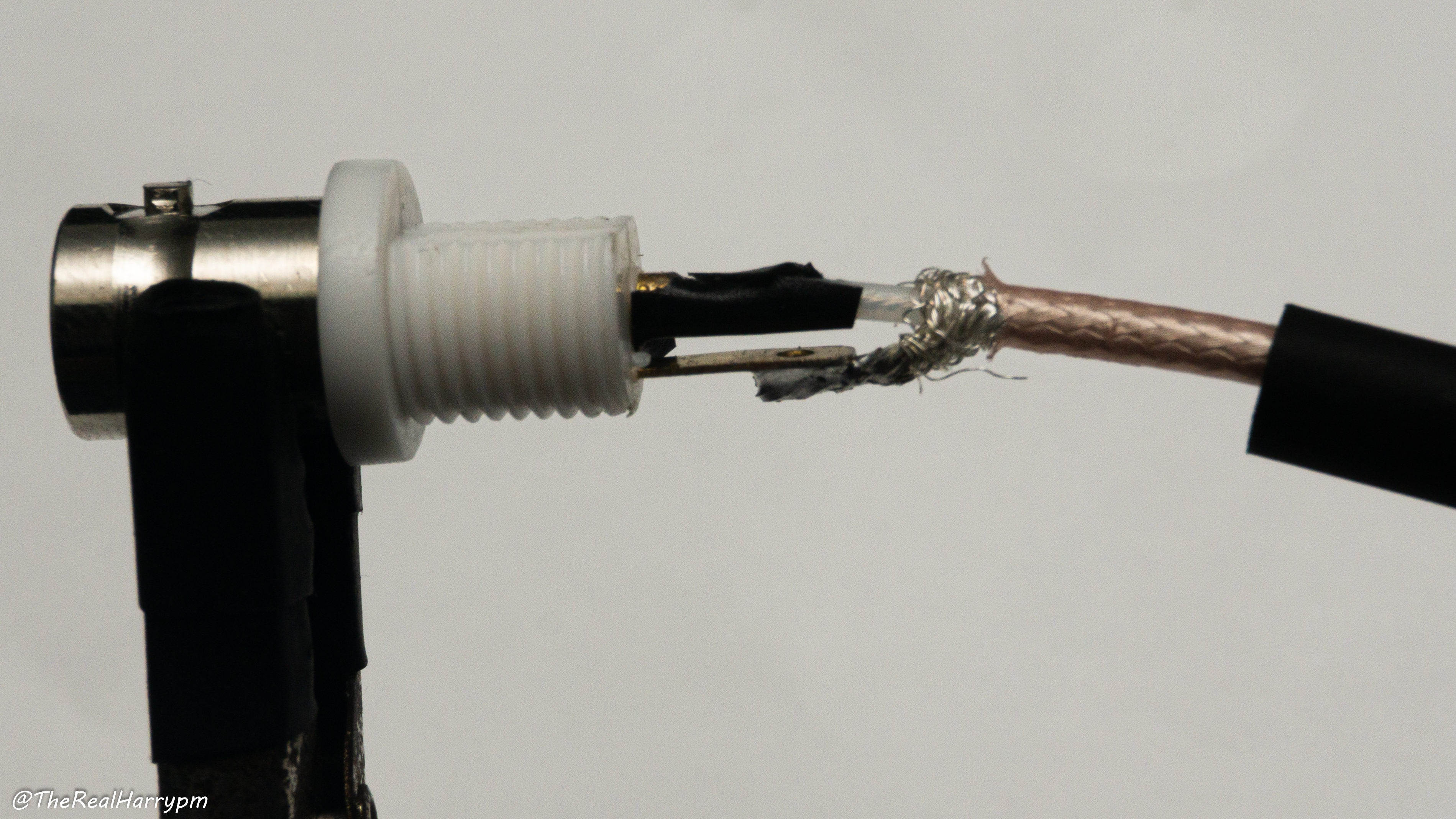
### Soldered Isolated BNC
> [!TIP]
> It's normally easier to tin the grounding leg then apply your tinned ground wire.
1. Use a bevel/flat tip (conical tips you can use but will be more fiddly)
2. Clean and flow a very small amount of fresh solder onto your Iron.
3. Add a small amount of flux into the centre pinhole, insert cable.
4. Holding the cable inside the connectors, then while pressing the pin gently with your iron push and flow solder into the open end of the connector until filled, but not overflowing.
5. Wipe excess flux off, after RF capture tests you can insulate this connector.
### Soldered Isolated BNC
> [!TIP]
> It's normally easier to tin the grounding leg then apply your tinned ground wire.
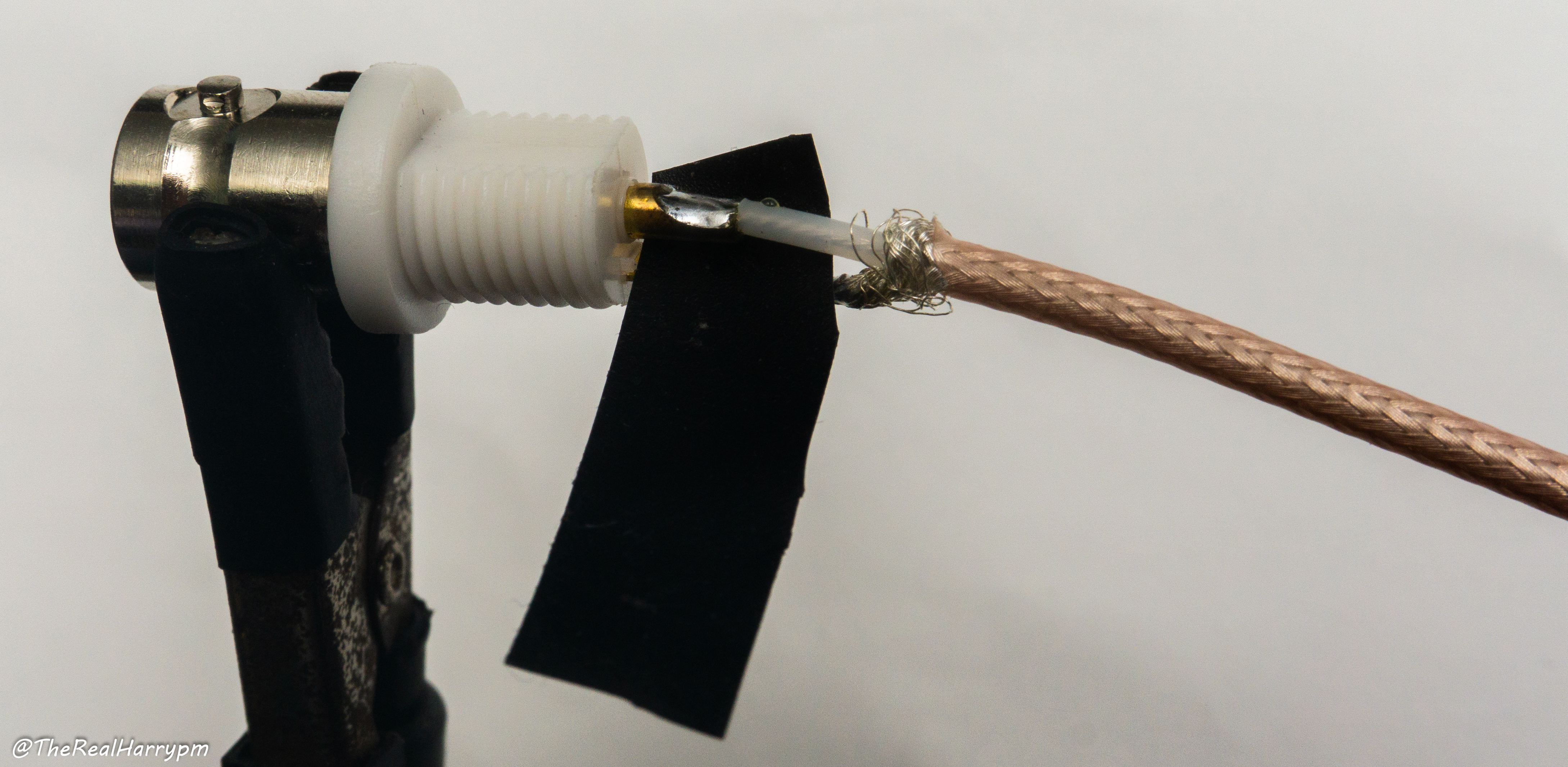
 ### Insulating Your Connectors
Once you know you have a good weld on the signal and ground solder joints this stops stray contact with dust and other wires.
You can do this with:
- Electric tape
- Heat-shrink
- Hot glue or silicone sealant
### Insulating Your Connectors
Once you know you have a good weld on the signal and ground solder joints this stops stray contact with dust and other wires.
You can do this with:
- Electric tape
- Heat-shrink
- Hot glue or silicone sealant
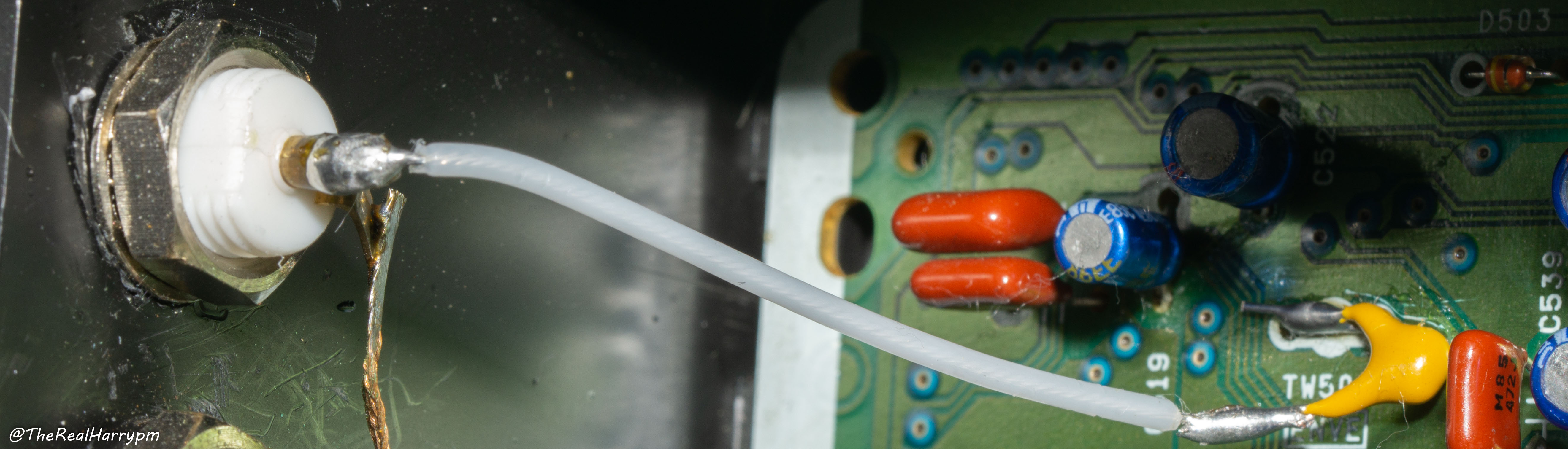
 # Step 05: Installing a capacitor on your RF tap
> [!CAUTION]
> If you are using or planning to use the [ADA4857 amplifier](Amplifier-Setup-Guide) (Step 6) you can skip installing a cap on your test points; there is one integrated into both inputs of the amplifier already.
## Bar Style
Example Used `Panasonic NV-HD630` HiFi RF Tap.
This is very simple in practice.
- Set your soldering iron to `280~320°C`
# Step 05: Installing a capacitor on your RF tap
> [!CAUTION]
> If you are using or planning to use the [ADA4857 amplifier](Amplifier-Setup-Guide) (Step 6) you can skip installing a cap on your test points; there is one integrated into both inputs of the amplifier already.
## Bar Style
Example Used `Panasonic NV-HD630` HiFi RF Tap.
This is very simple in practice.
- Set your soldering iron to `280~320°C`
 - Lay your capacitor next to flat bar types or curl one leg around for floating/poll types.
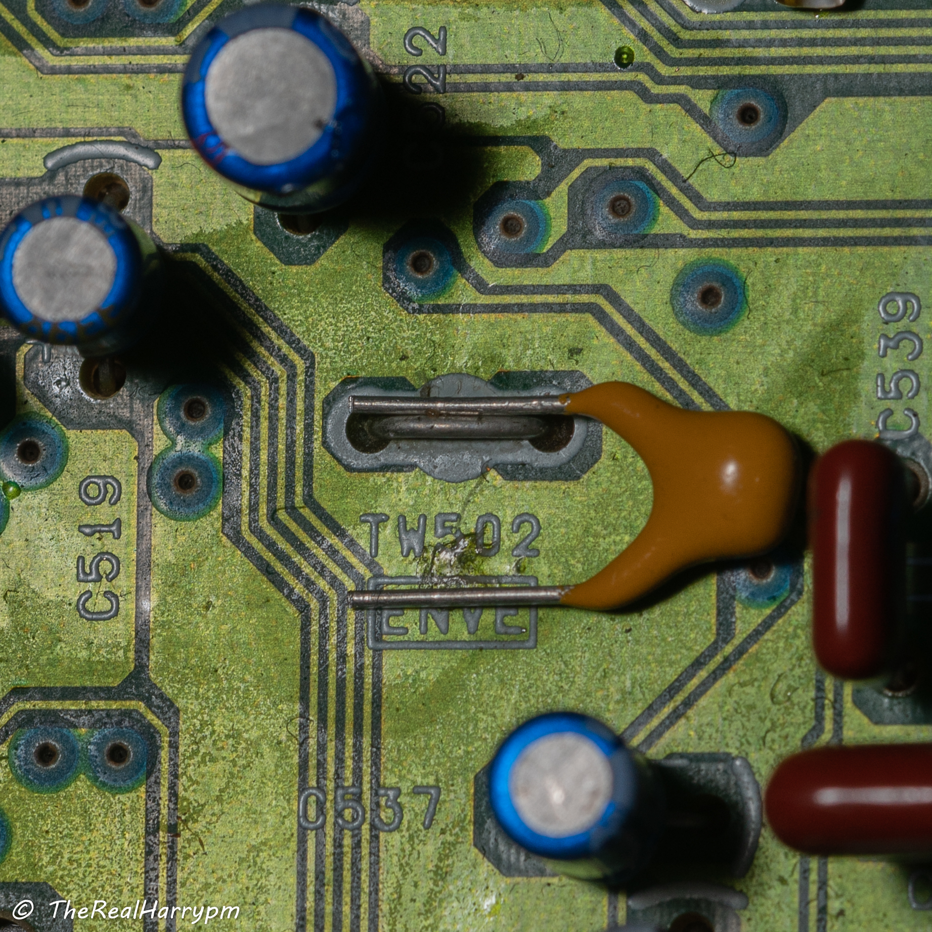 - Apply flux to the joint, then liquify with a light touch by your iron and ensure position is correct.
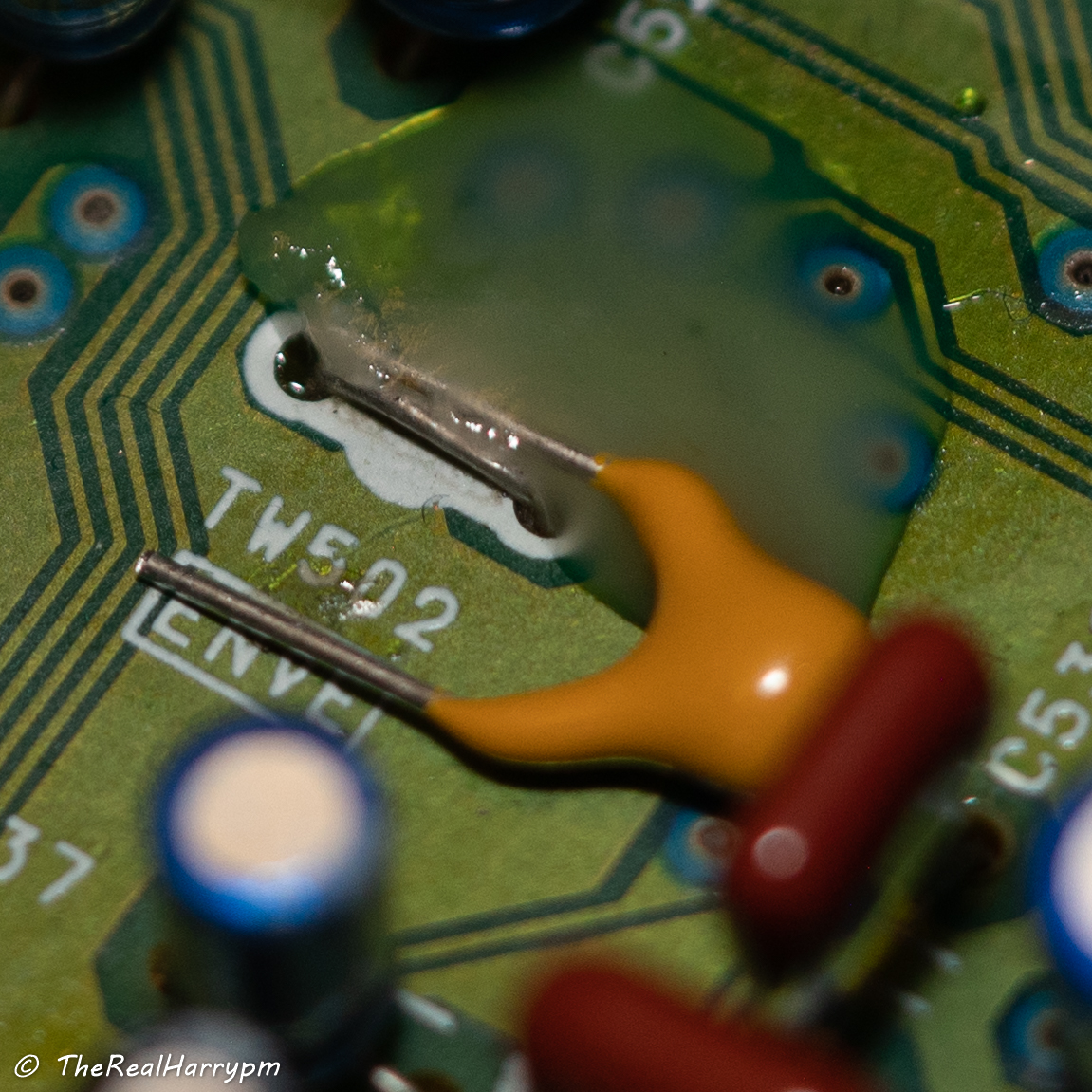 - Apply solder to your iron, a bevel or chisel tip is better than a conical rounded tip for this use but either work fine.
 - Apply your tinned iron to the joint and allow 1-2 seconds to flow then move your iron away, it is easy to knock flat bar types, so it's best to ensure the legs lay perfectly flat to the board level with the test point.
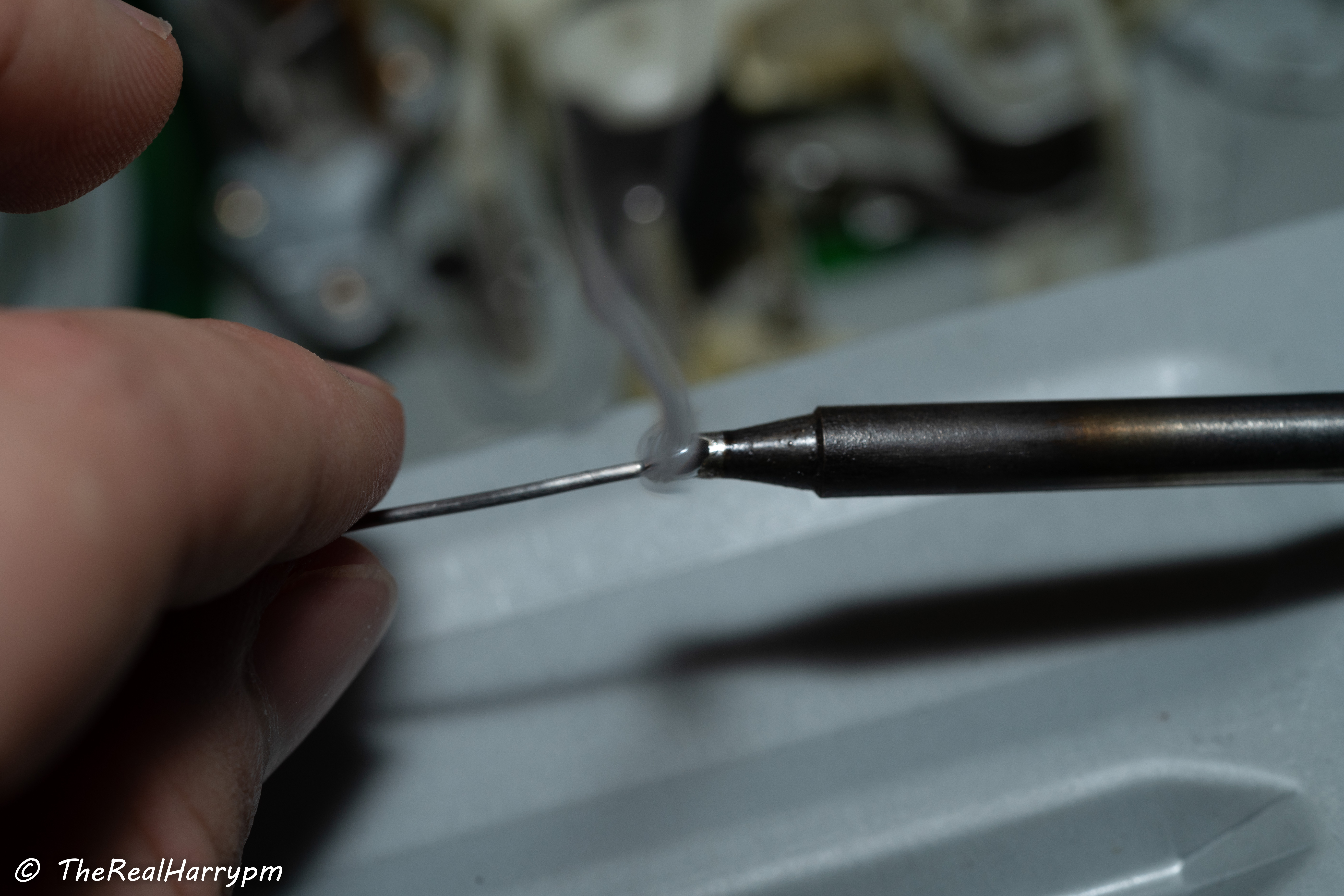
 - Always clean your soldering area with 99.9% IPA after you are done to remove any flux.
- Clean Your Tip
- Always clean your soldering area with 99.9% IPA after you are done to remove any flux.
- Clean Your Tip
 - Connect your BNC with soldering a cable end to end.
> [!NOTE]
> Very short runs can get away with no shielding in most cases, but should always be shielded if a long run or passing by EMI sensitive parts and ground extended via secondary wire.
- Tin your Tip and disconnect your iron for storage, the coat helps protect it from rusting.
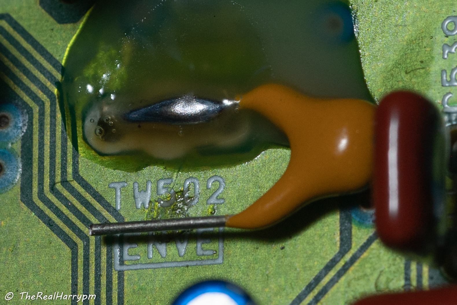
## What NOT to do!
> [!CAUTION]
> If flux is not applied, poor quality solder used or not enough heat, it will never properly flow if using stranded coax wire it's best to twist it together, then tin it with a litte solder before adding a capacitor leg onto it, or a leg onto the test point first.
> [!TIP]
> Cold joints are soldered joints formed when the metals don't make a proper weld together, and ball up or look dull.
- Connect your BNC with soldering a cable end to end.
> [!NOTE]
> Very short runs can get away with no shielding in most cases, but should always be shielded if a long run or passing by EMI sensitive parts and ground extended via secondary wire.
- Tin your Tip and disconnect your iron for storage, the coat helps protect it from rusting.
## What NOT to do!
> [!CAUTION]
> If flux is not applied, poor quality solder used or not enough heat, it will never properly flow if using stranded coax wire it's best to twist it together, then tin it with a litte solder before adding a capacitor leg onto it, or a leg onto the test point first.
> [!TIP]
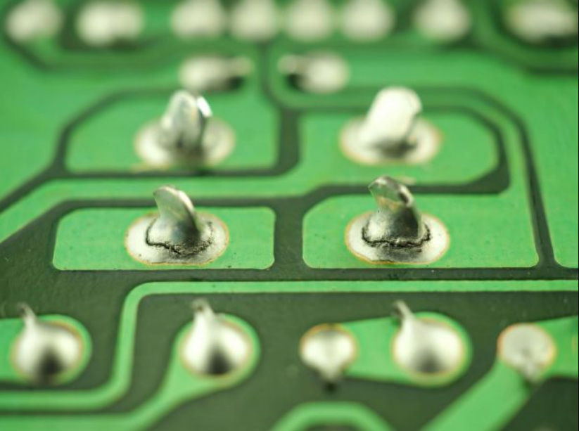
> Cold joints are soldered joints formed when the metals don't make a proper weld together, and ball up or look dull.
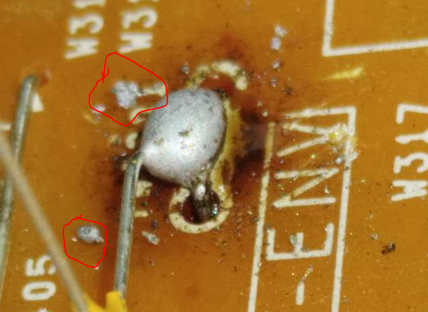
 > [!CAUTION]
> Incorrect cabling, blobby soldering should be avoided & cold/cracked joints should always be reflowed.
> [!CAUTION]
> Incorrect cabling, blobby soldering should be avoided & cold/cracked joints should always be reflowed.
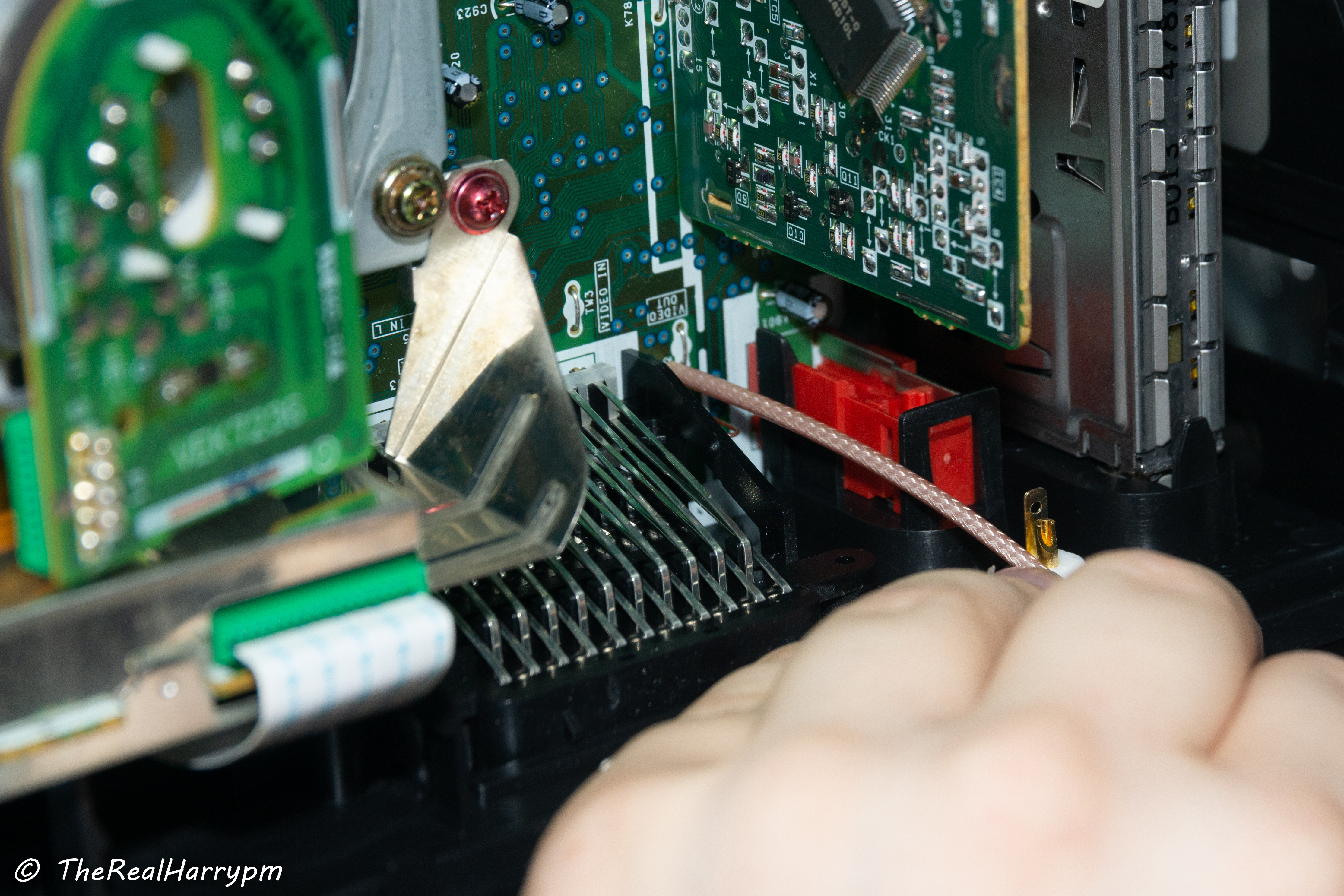
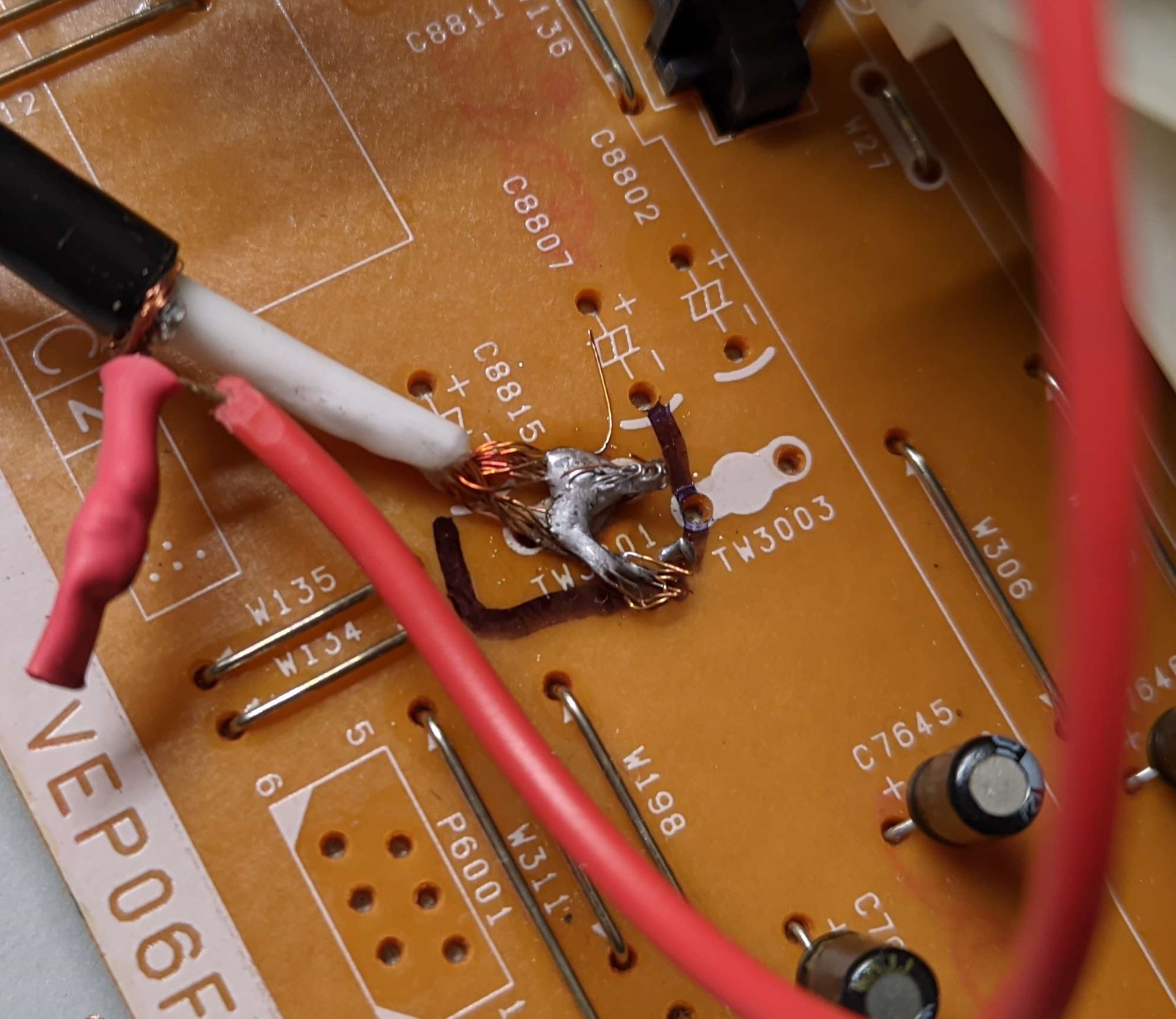
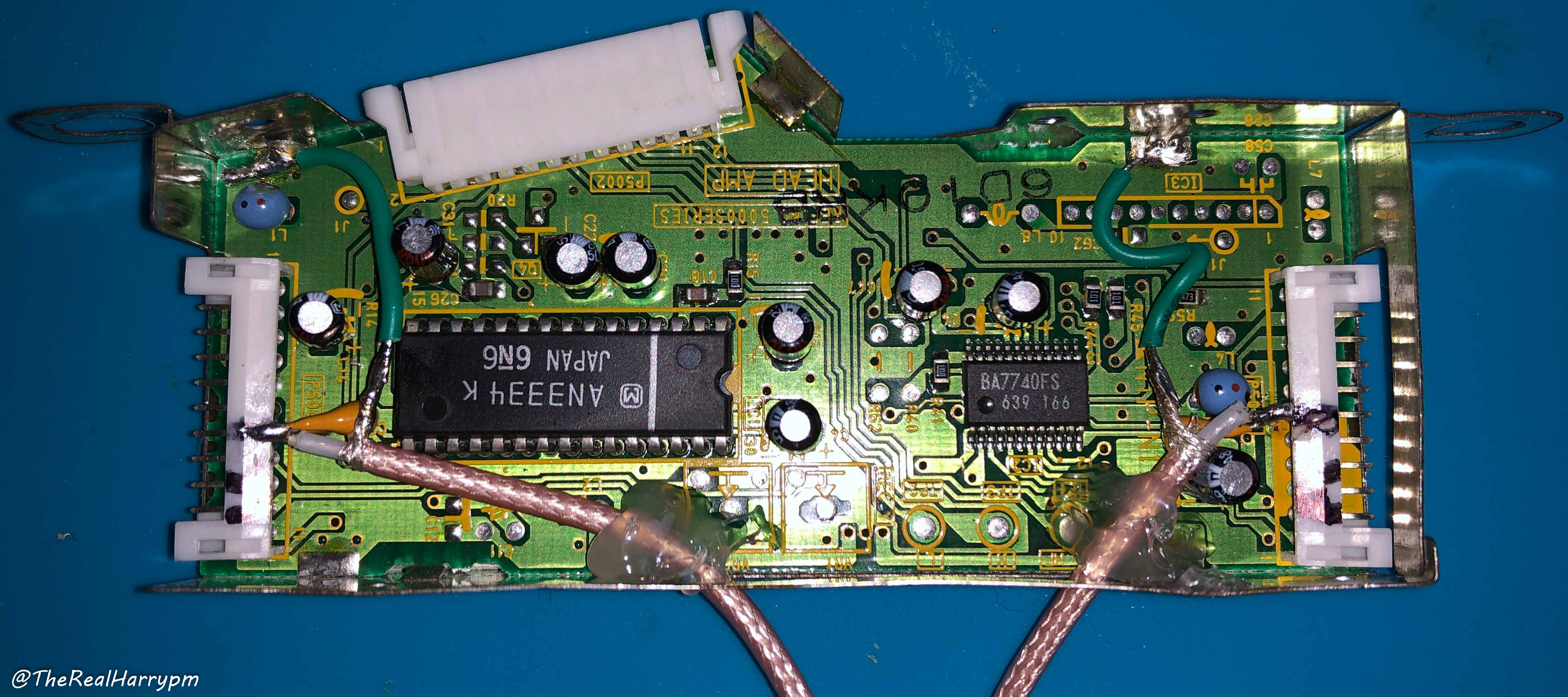
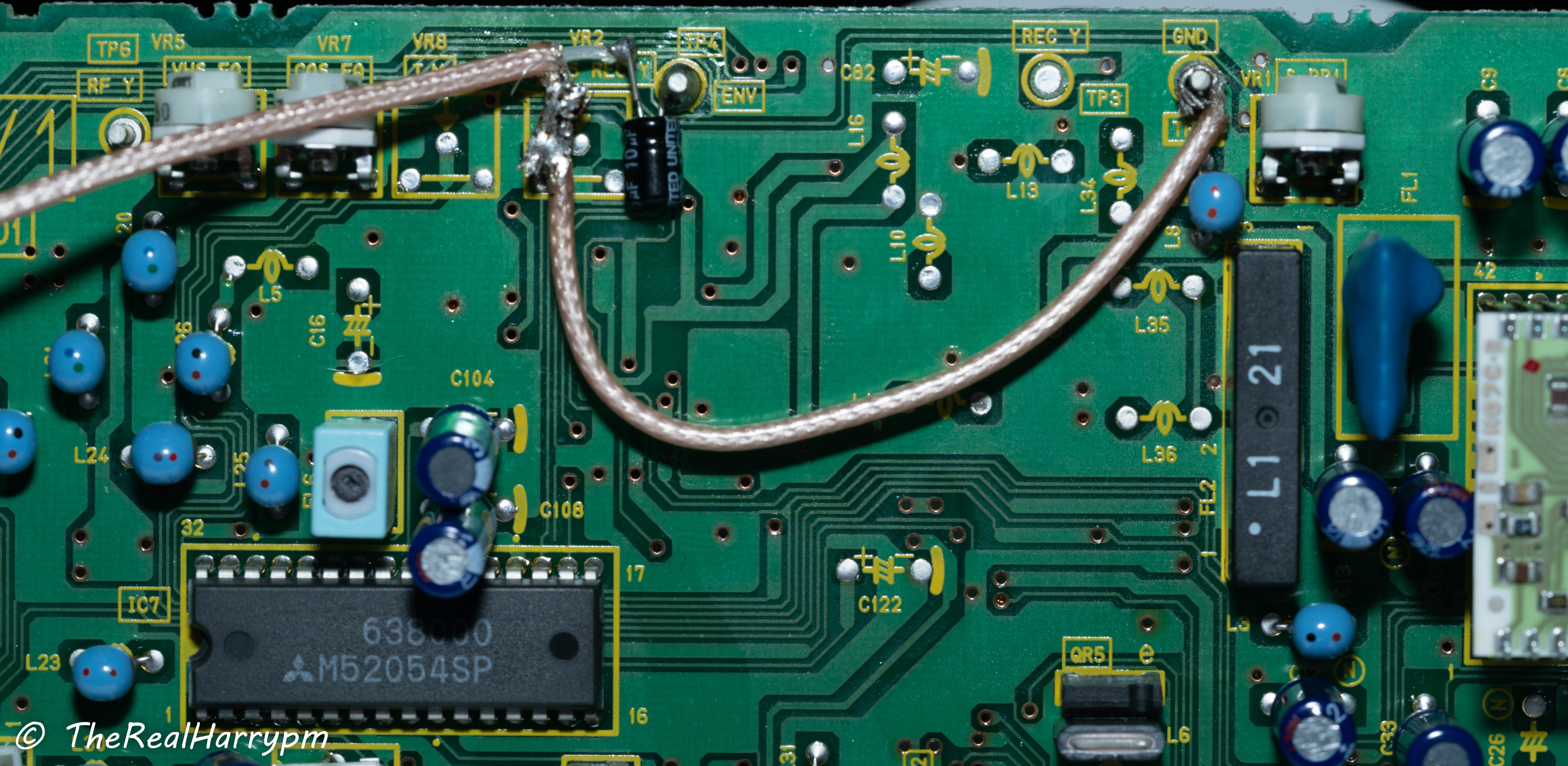
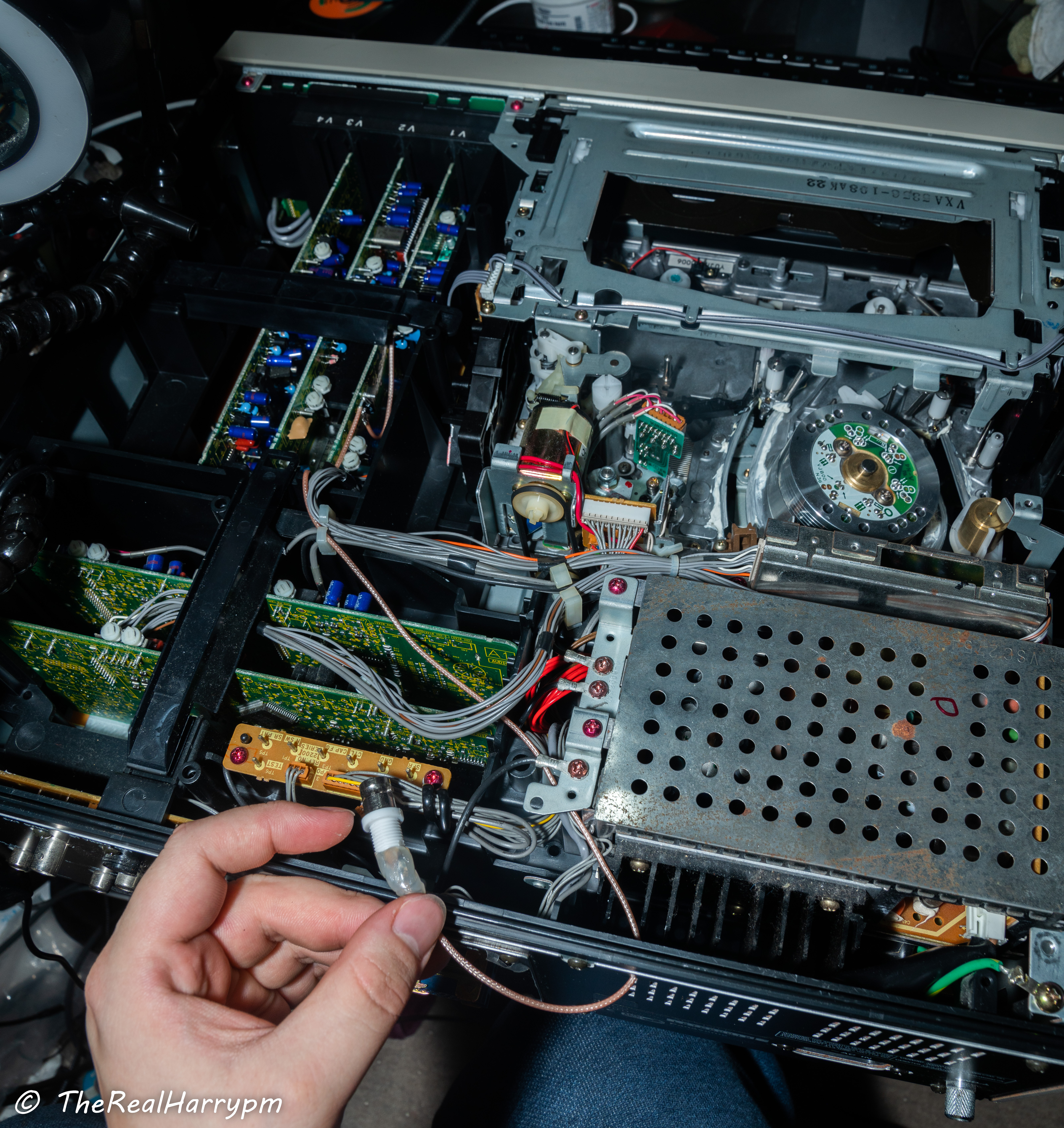
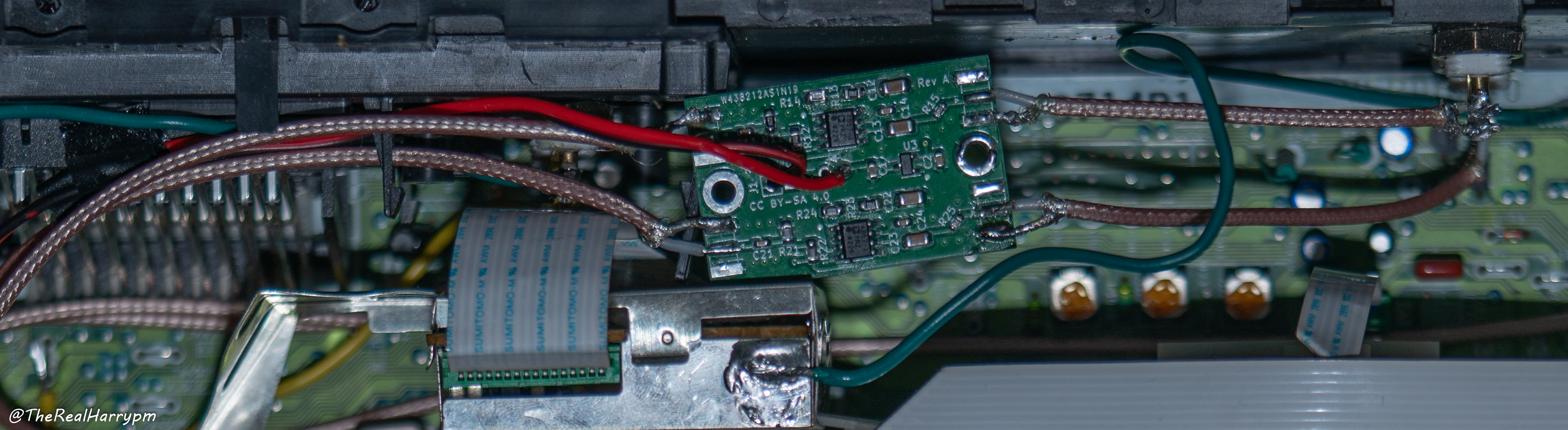
 ## Direct Head Amplifier Style
More common on higher end & 90s prosumer decks, thanks to easy removal of the head amplifier pack, and due to filtering on hifi and just more potential losses in the signal path direct head amp tapping is a lot more practical and flexible for the experienced in soldering.
The most ideal cabling is a re-enforced SMA or SMB male or female line this allows you to easily connect up cables to amplifiers as is small and compact enough for in-chassis use.
## Direct Head Amplifier Style
More common on higher end & 90s prosumer decks, thanks to easy removal of the head amplifier pack, and due to filtering on hifi and just more potential losses in the signal path direct head amp tapping is a lot more practical and flexible for the experienced in soldering.
The most ideal cabling is a re-enforced SMA or SMB male or female line this allows you to easily connect up cables to amplifiers as is small and compact enough for in-chassis use.
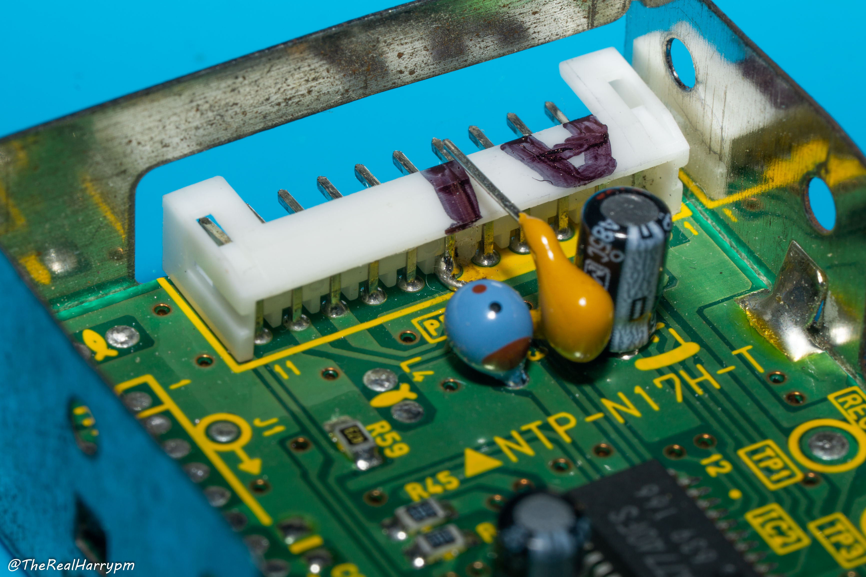
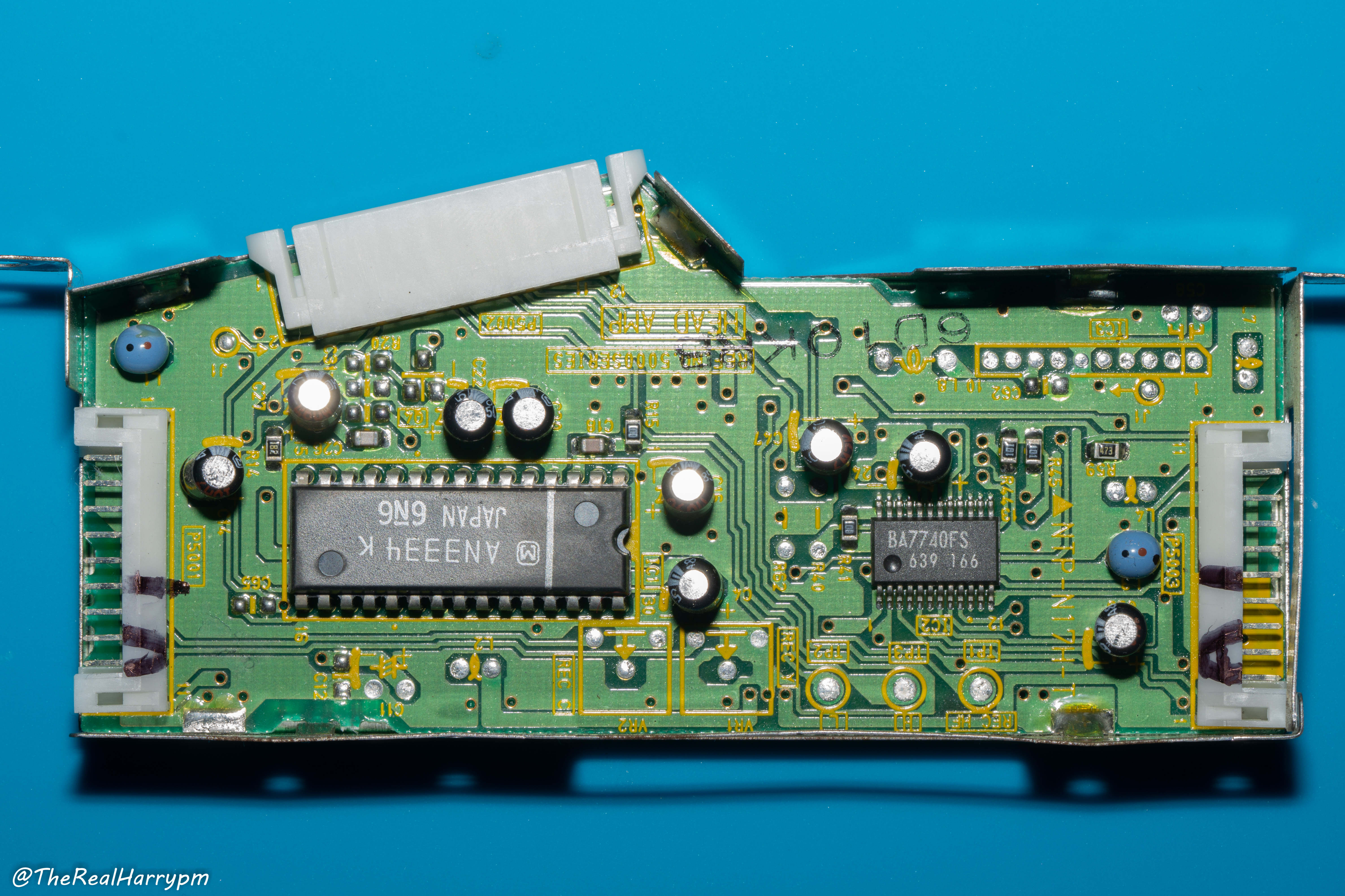 Instead of tapping the ICs directly, we simply hijack the PCB connectors going to the rest of the VCR.
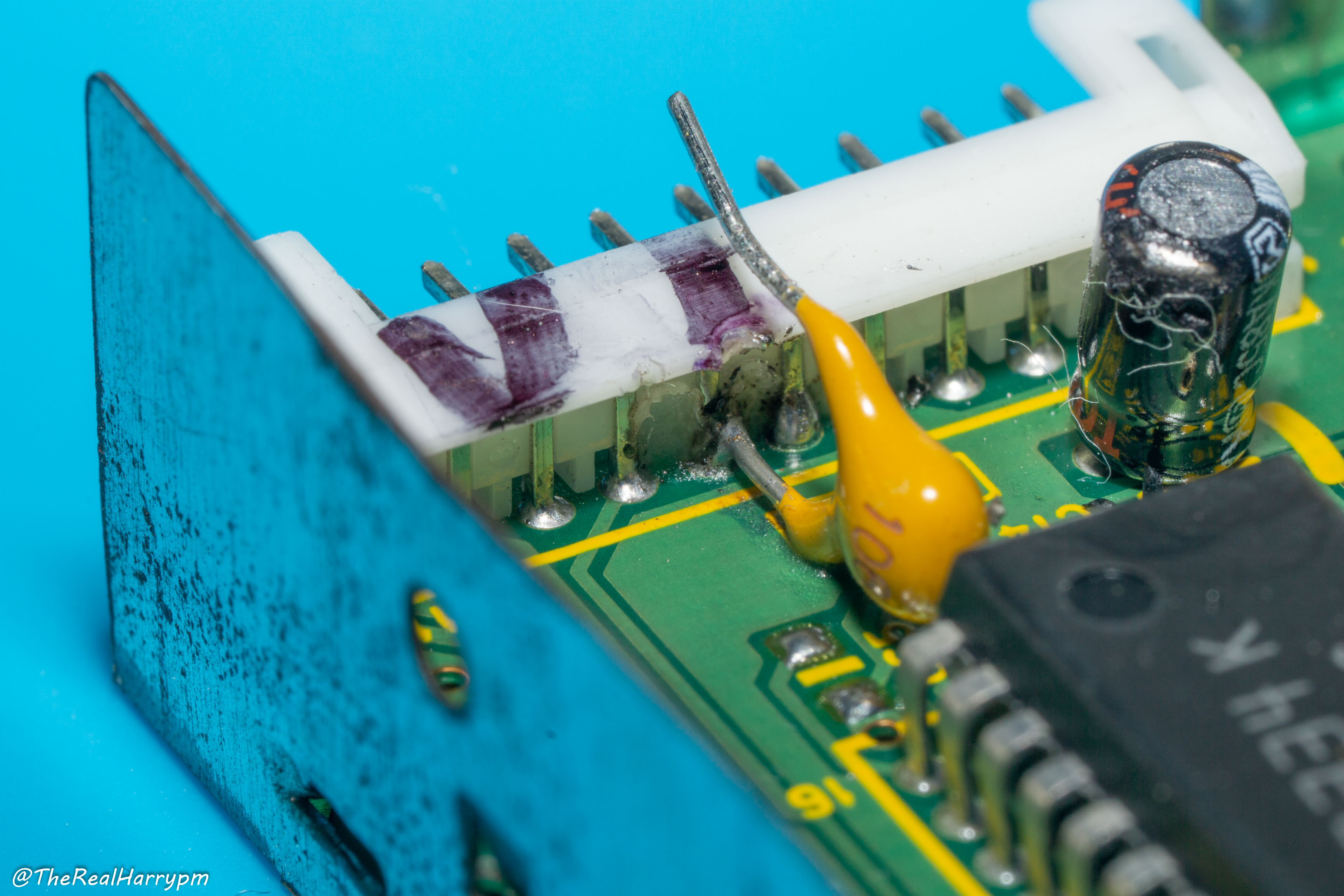 Tapping into the pins of the ICs directly is more ideal in some cases. If you feel comfortable with that, you must ensure mechanical strain relief so you never damage or rip legs off the PCB pads or ICs themselves.
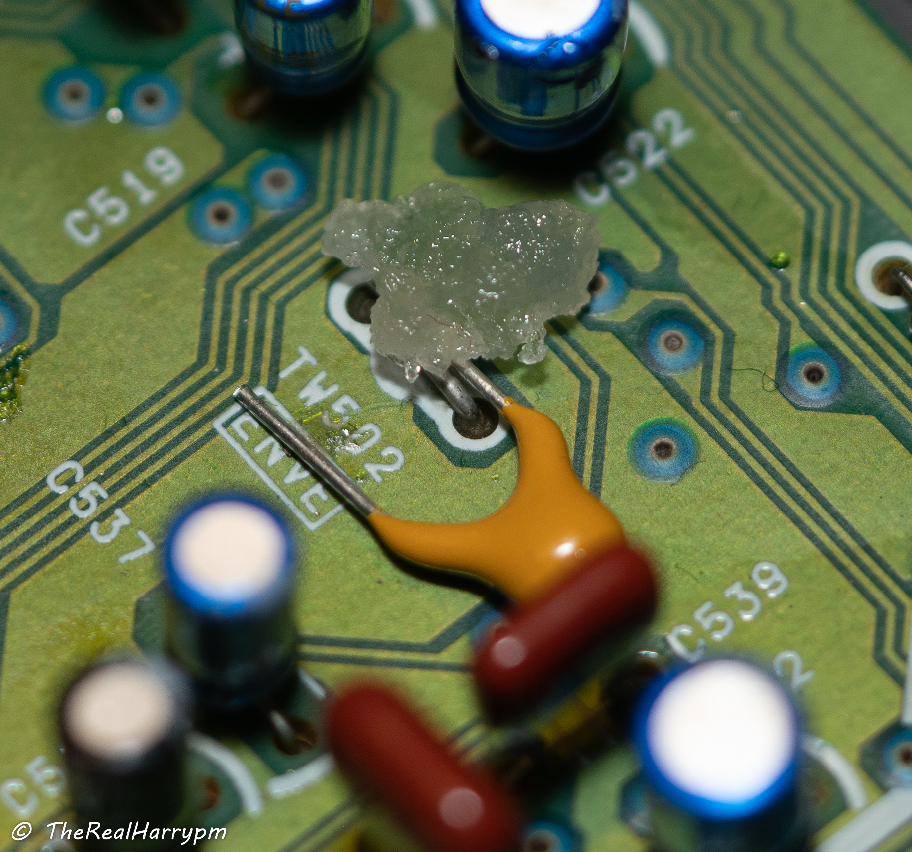
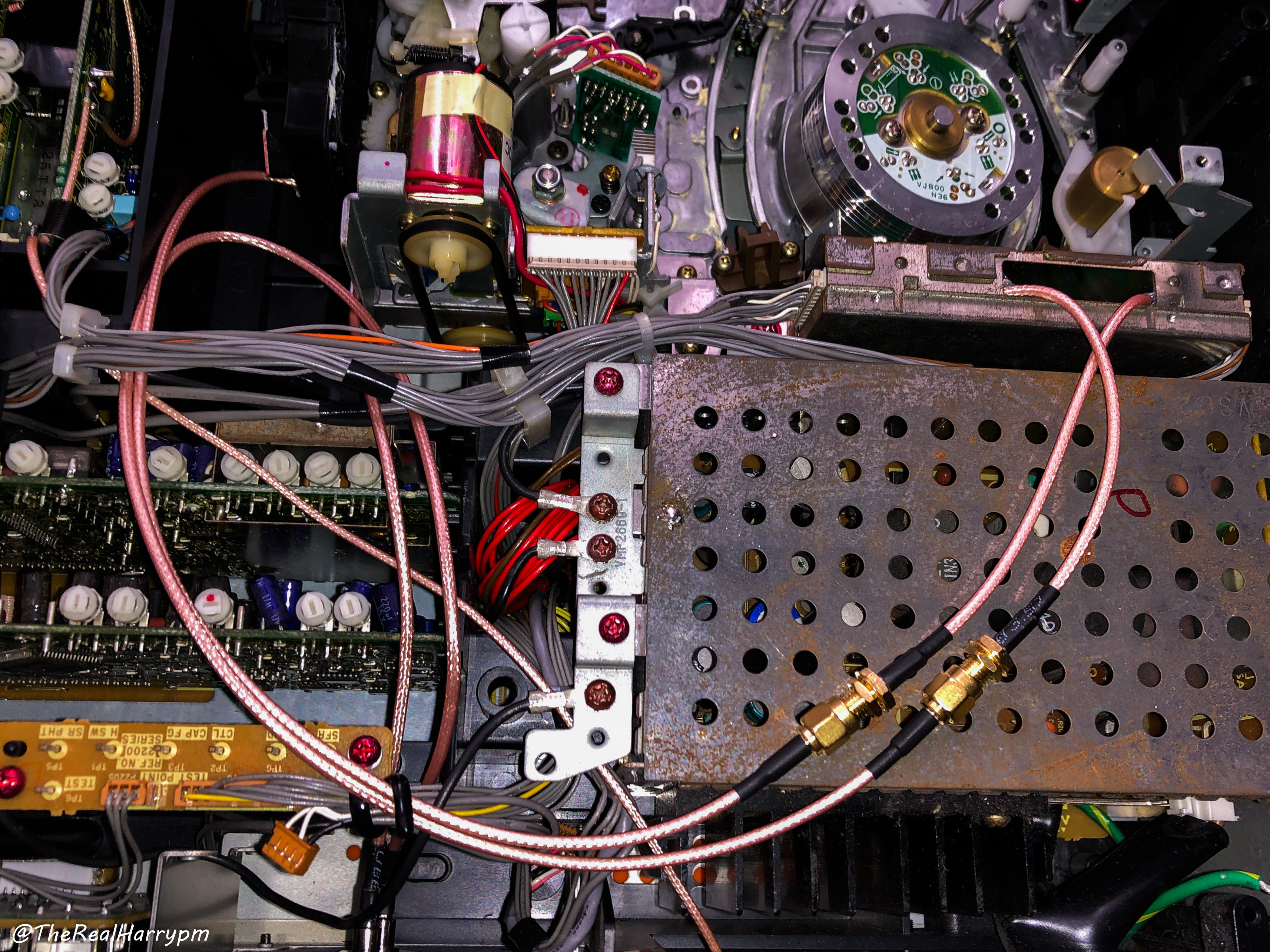
 Then secure cables with hot glue ensuring no stress on the tap points.
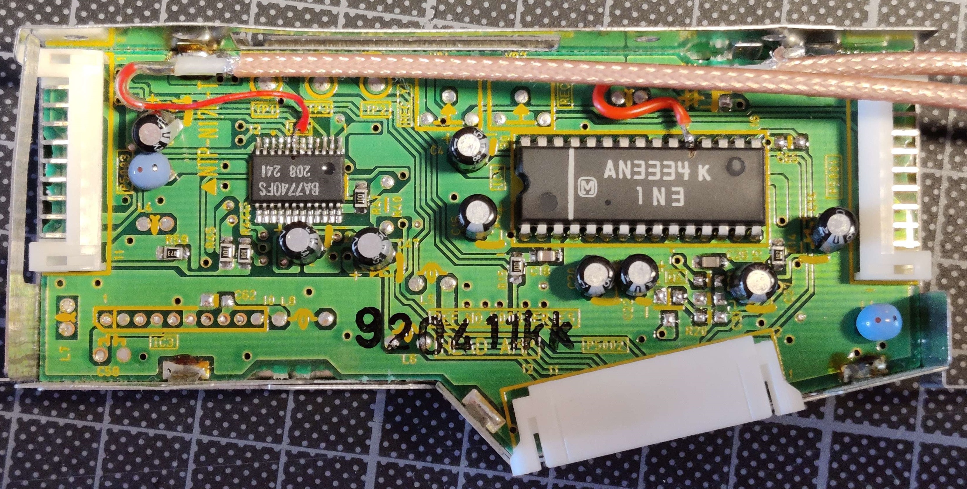
 The SMA connections can then go directly to BNCs on a 3D printed backplate module or have an amplifier in-line.
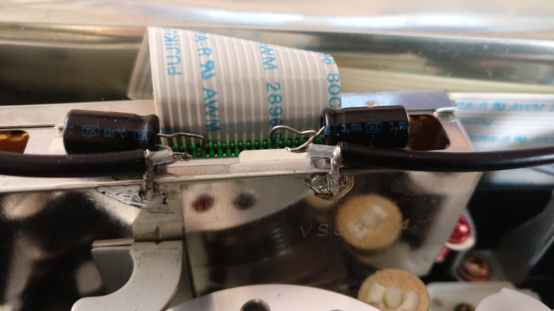
 ## Push Pin Style
Example Used `Panasonic NV-HS1000` & `Panasonic NV-HS950B`
- If you can do pin-push method on an amplifier board then manipulate the legs with tweezers carefully, and insert the leg cable side if you push from plastic side you might damage the connector pin.
- Strip your RG Coax cable and twist the grounding together and apply flux to it
- Solder your grounding to the exterior shield of the head amplifier
- Route your cables to the back of the VCR to BNC Bulkheads or though vents.
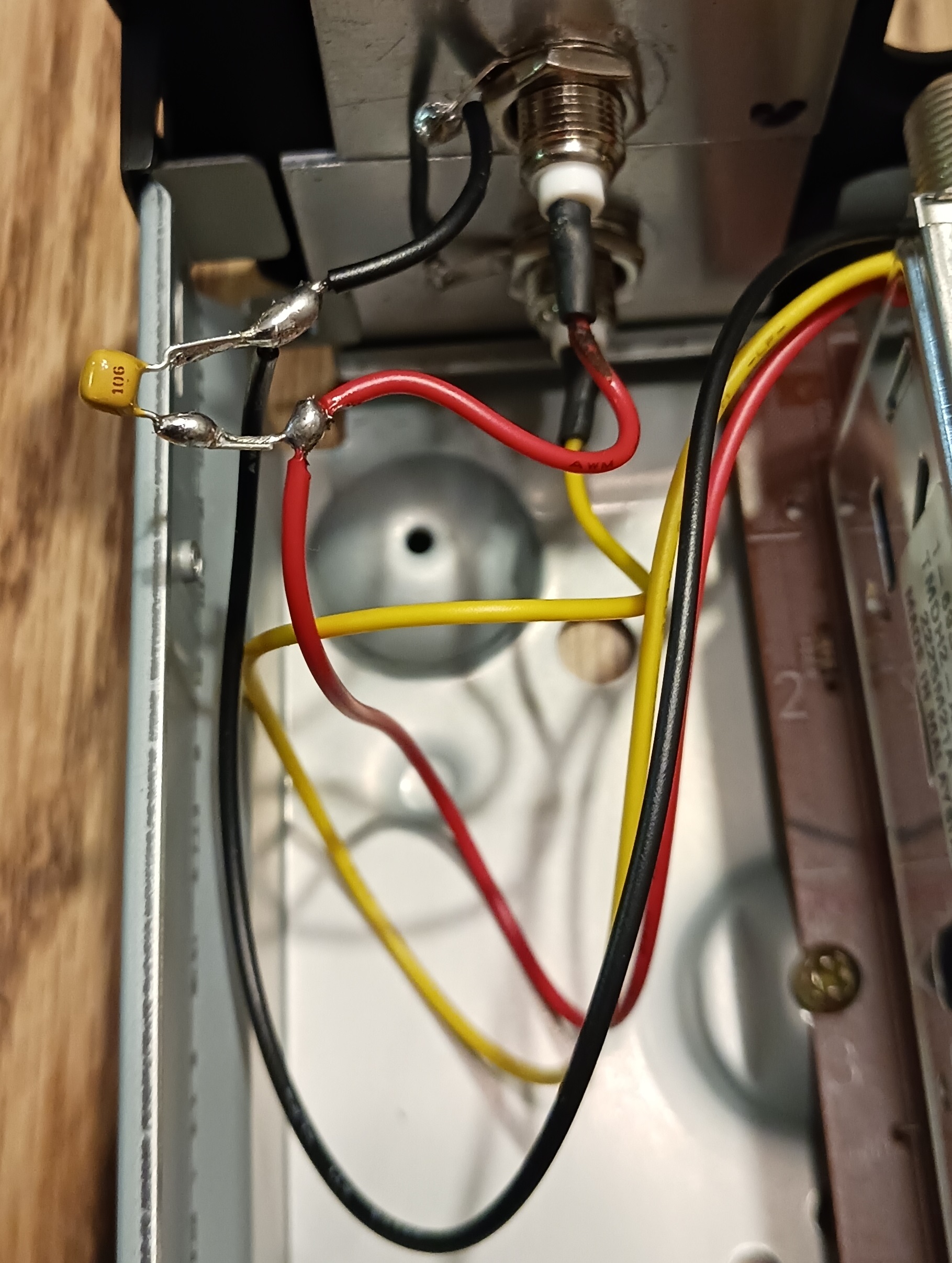
## Flat Bar Style
> [!CAUTION]
> Older examples with electrolytic caps, ceramic caps are recommended today as they are non-polarised.
## Push Pin Style
Example Used `Panasonic NV-HS1000` & `Panasonic NV-HS950B`
- If you can do pin-push method on an amplifier board then manipulate the legs with tweezers carefully, and insert the leg cable side if you push from plastic side you might damage the connector pin.
- Strip your RG Coax cable and twist the grounding together and apply flux to it
- Solder your grounding to the exterior shield of the head amplifier
- Route your cables to the back of the VCR to BNC Bulkheads or though vents.
## Flat Bar Style
> [!CAUTION]
> Older examples with electrolytic caps, ceramic caps are recommended today as they are non-polarised.
 (If both legs are even then this is a non-polarised cap and does not matter.)
You can test your test points with a 10-sec capture at this point with no displays connected via probes.
Once your test points have been located, depending on your available space, you will want to line up or lay your 3.3-10uf range capacitor next to for bar style or wrap half around for poll style test points, holding it down with tweezers or via tape/hot glue.
> [!NOTE]
> Polymer and ceramic capacitors, these are not polarised so which of the 2 legs are used does not matter, for electrolytic capacitors the positive leg goes into the test point and the negative to your cable.
> [!CAUTION]
> The Negative leg is always the shorter of the two which makes it easy to visually identify, for bidirectional parts its always equal
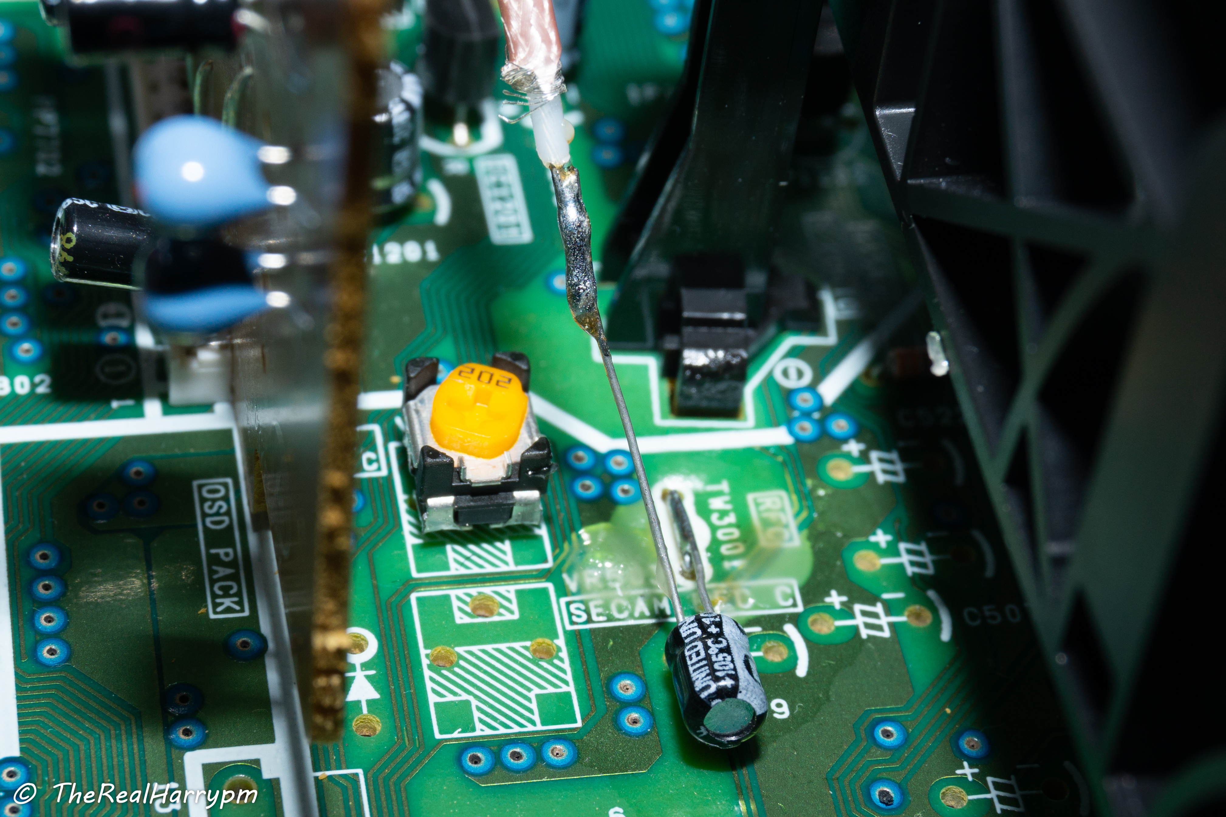
## Poll Style
*Using an easy example here, as the rackmount decks have removable Audio/Video cards.*
Example Used: `Panasonic AG7150` & `Panasonic NV-HS950B`
- Line up your capacitor to the test point, make a 90 degree U bend then cut the excess off.
- Apply flux to the test point to ensure good solder flow.
- Tin your iron and give it a clean, then tin again and flow some solder onto the leg and test point leg wire.
(If both legs are even then this is a non-polarised cap and does not matter.)
You can test your test points with a 10-sec capture at this point with no displays connected via probes.
Once your test points have been located, depending on your available space, you will want to line up or lay your 3.3-10uf range capacitor next to for bar style or wrap half around for poll style test points, holding it down with tweezers or via tape/hot glue.
> [!NOTE]
> Polymer and ceramic capacitors, these are not polarised so which of the 2 legs are used does not matter, for electrolytic capacitors the positive leg goes into the test point and the negative to your cable.
> [!CAUTION]
> The Negative leg is always the shorter of the two which makes it easy to visually identify, for bidirectional parts its always equal
## Poll Style
*Using an easy example here, as the rackmount decks have removable Audio/Video cards.*
Example Used: `Panasonic AG7150` & `Panasonic NV-HS950B`
- Line up your capacitor to the test point, make a 90 degree U bend then cut the excess off.
- Apply flux to the test point to ensure good solder flow.
- Tin your iron and give it a clean, then tin again and flow some solder onto the leg and test point leg wire.
 - Run the outer shield to the ground or run a separate cable for grounding.
> [!NOTE]
> Coax shields the signal wire with its grounding path wire wrapping around the insulation.
- If possible mount to BNC bulkhead on a plate, route though vents or simply you can also hijack an redundant CVBS BNC if avalible.
- Run the outer shield to the ground or run a separate cable for grounding.
> [!NOTE]
> Coax shields the signal wire with its grounding path wire wrapping around the insulation.
- If possible mount to BNC bulkhead on a plate, route though vents or simply you can also hijack an redundant CVBS BNC if avalible.
 # Step 06: Amplifier Setup
> [!WARNING]
> - This section is in its own [dedicated wiki page](Amplifier-Setup-Guide), as amplifiers are meant to be deployed after the initial setup and testing phase of tapping a device for FM RF capture use, so you have a baseline (does this deck work, is a cap in-line a bare-minimum requirement, etc.).
>
> - Amplifiers can be deployed directly if you plan and prepare ahead of time. They also have a 10 uf cap on the input ends, so you no longer need one on the test point and can do direct wire runs.
>
> - DdD & MISRC both have internal amplifiers of high quality, so while an in-deck amplifier may not be 100% needed just for amplifying, it will provide the critical purpose of proper impedance setting to limit signal draw and potential artefacts from said signal draw on your VCR/VTR's head pre-amplifier, such as cross-hatching.
## [The AD4857 Amplifier Install Guide](Amplifier-Setup-Guide)
# Step 06: Amplifier Setup
> [!WARNING]
> - This section is in its own [dedicated wiki page](Amplifier-Setup-Guide), as amplifiers are meant to be deployed after the initial setup and testing phase of tapping a device for FM RF capture use, so you have a baseline (does this deck work, is a cap in-line a bare-minimum requirement, etc.).
>
> - Amplifiers can be deployed directly if you plan and prepare ahead of time. They also have a 10 uf cap on the input ends, so you no longer need one on the test point and can do direct wire runs.
>
> - DdD & MISRC both have internal amplifiers of high quality, so while an in-deck amplifier may not be 100% needed just for amplifying, it will provide the critical purpose of proper impedance setting to limit signal draw and potential artefacts from said signal draw on your VCR/VTR's head pre-amplifier, such as cross-hatching.
## [The AD4857 Amplifier Install Guide](Amplifier-Setup-Guide)
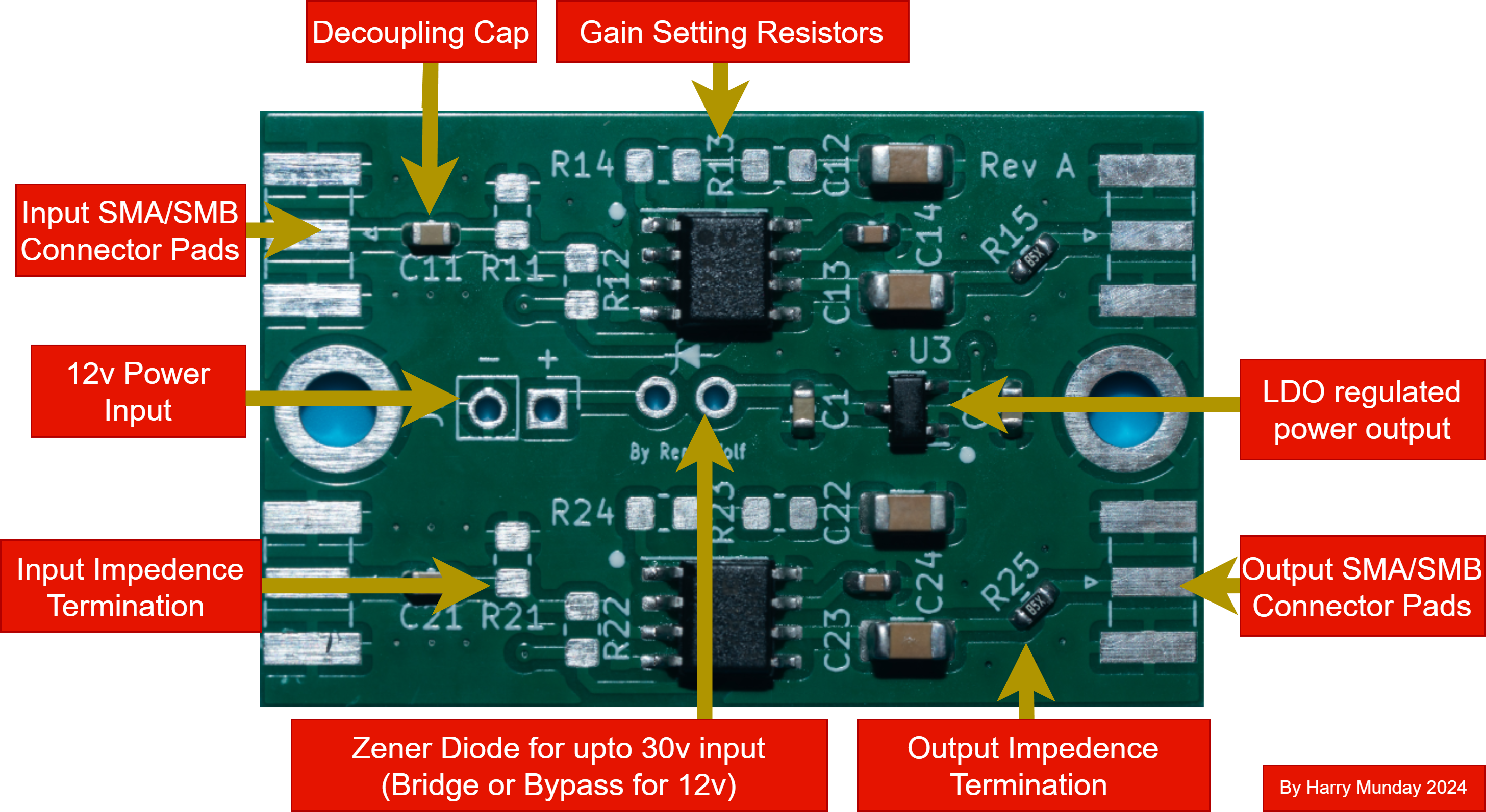 > [!NOTE]
> The Input impedance resistors are 2 for each path with each path using 2 resistors of the same value.
There are three parts to this process:
- `finding your output resistance` (this sets your input termination)
- `finding your gain level` (this is what you base your gain setting off)
- `find a stable 5~18v power source from internal test points or use external PSU/Battery`
This is physically configured via 4 SMD 0805 resistors on each of the two channels.
You use 2x the same value for input resistance, and 2x for gain control level according to the values table.
# RF Tap Setup Examples
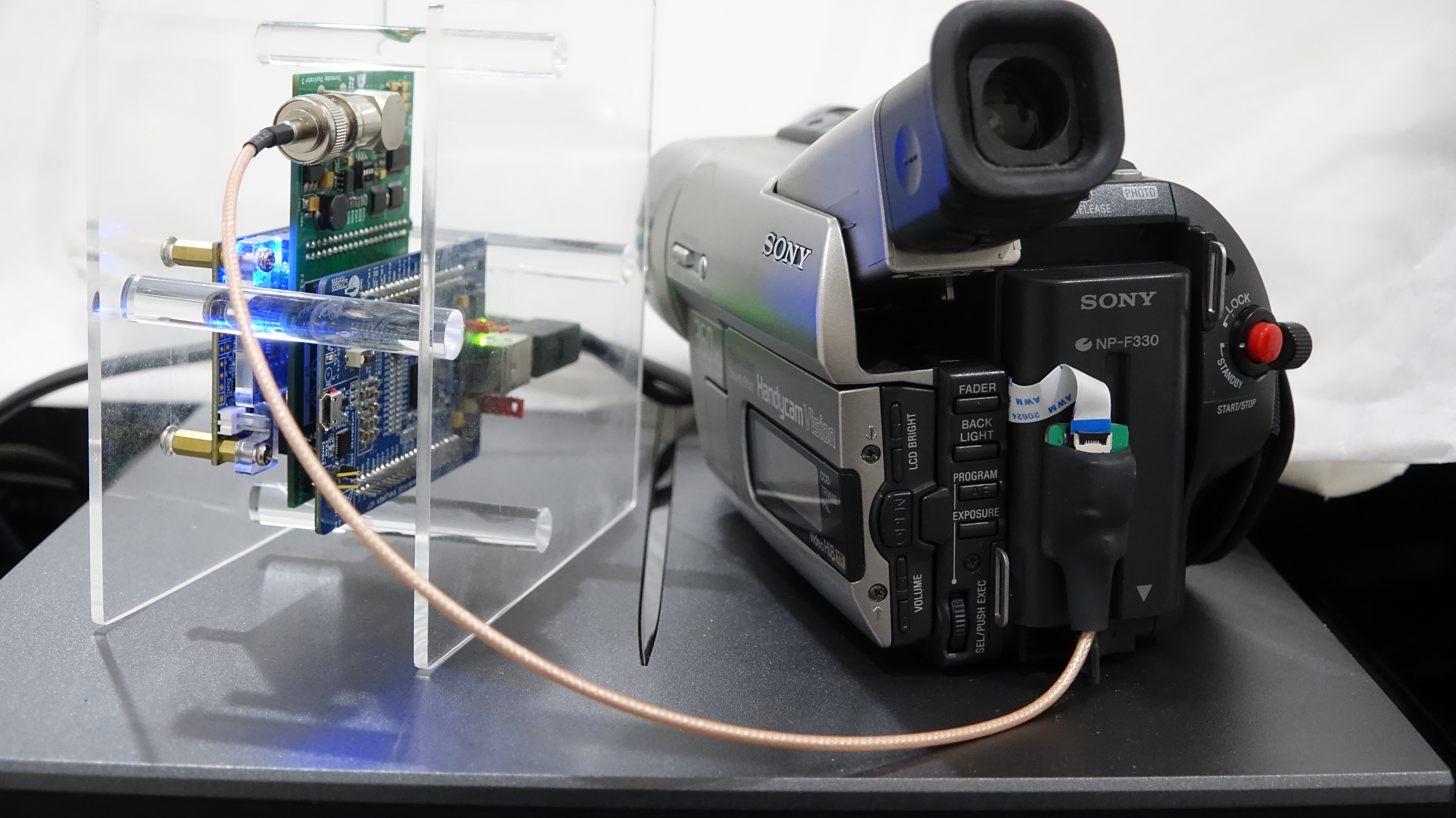
## Sony 8mm Camcorders
Sony-Hi8-CCD-TRV66E
> [!NOTE]
> The Input impedance resistors are 2 for each path with each path using 2 resistors of the same value.
There are three parts to this process:
- `finding your output resistance` (this sets your input termination)
- `finding your gain level` (this is what you base your gain setting off)
- `find a stable 5~18v power source from internal test points or use external PSU/Battery`
This is physically configured via 4 SMD 0805 resistors on each of the two channels.
You use 2x the same value for input resistance, and 2x for gain control level according to the values table.
# RF Tap Setup Examples
## Sony 8mm Camcorders
Sony-Hi8-CCD-TRV66E
 Sony-Digital8-DCR-TRV238E
 ## VHS Decks
Panasonic NV-HS950B TBC Card Video ENV Tap routed through the frame.
## VHS Decks
Panasonic NV-HS950B TBC Card Video ENV Tap routed through the frame.
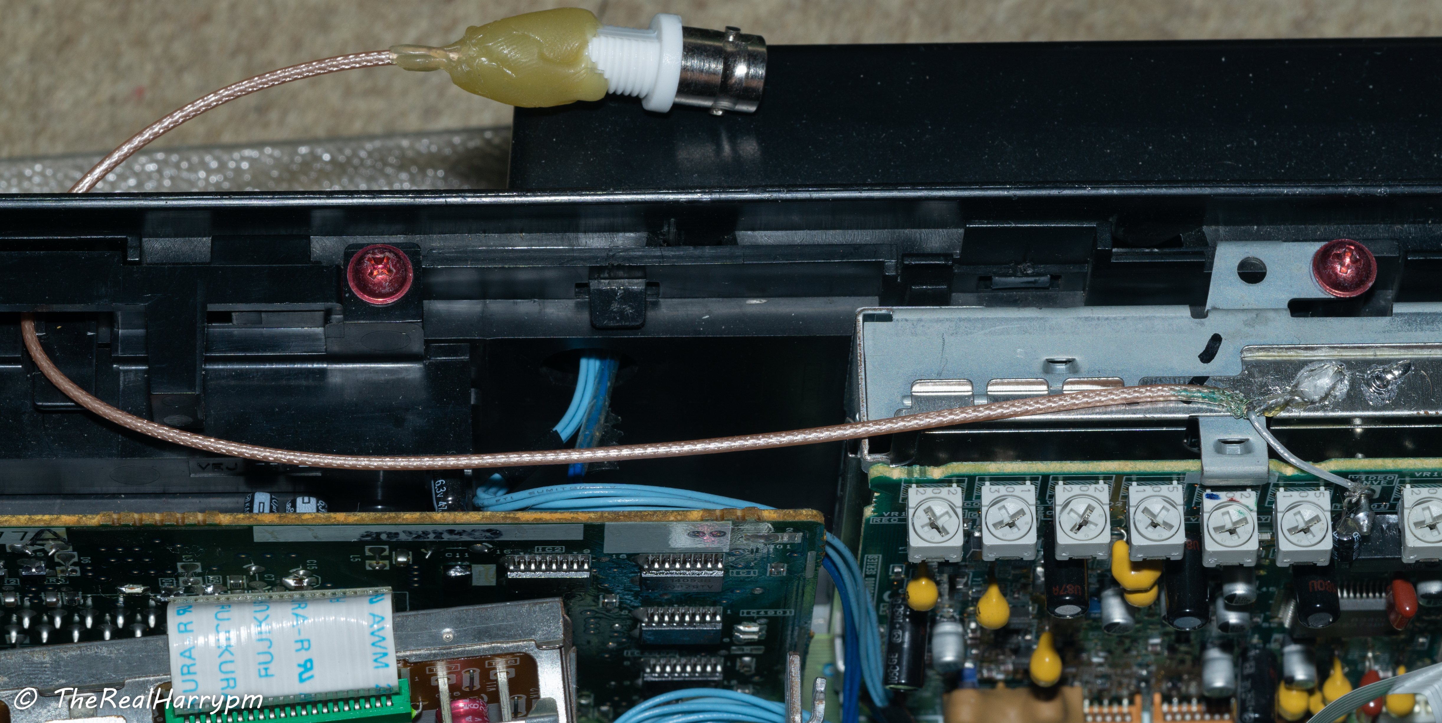 -----
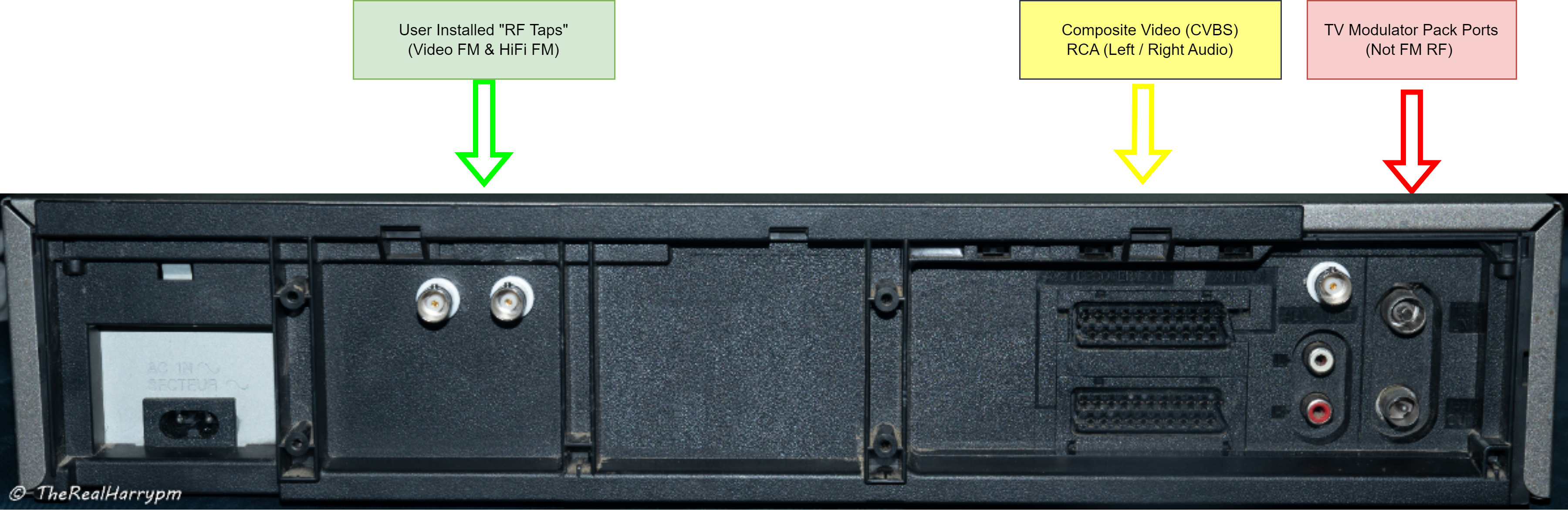
Panasonic NV-HD630B Video/HiFi FM & and extra composite tap mounted to BNC Bulkheads.
-----
Panasonic NV-HD630B Video/HiFi FM & and extra composite tap mounted to BNC Bulkheads.
 ----
Panasonic NV-HD630B with ADA4857 amplifier.
Video RF + HiFi RF routed to the amplifier then to BNC bulkheads.
----
Panasonic NV-HD630B with ADA4857 amplifier.
Video RF + HiFi RF routed to the amplifier then to BNC bulkheads.
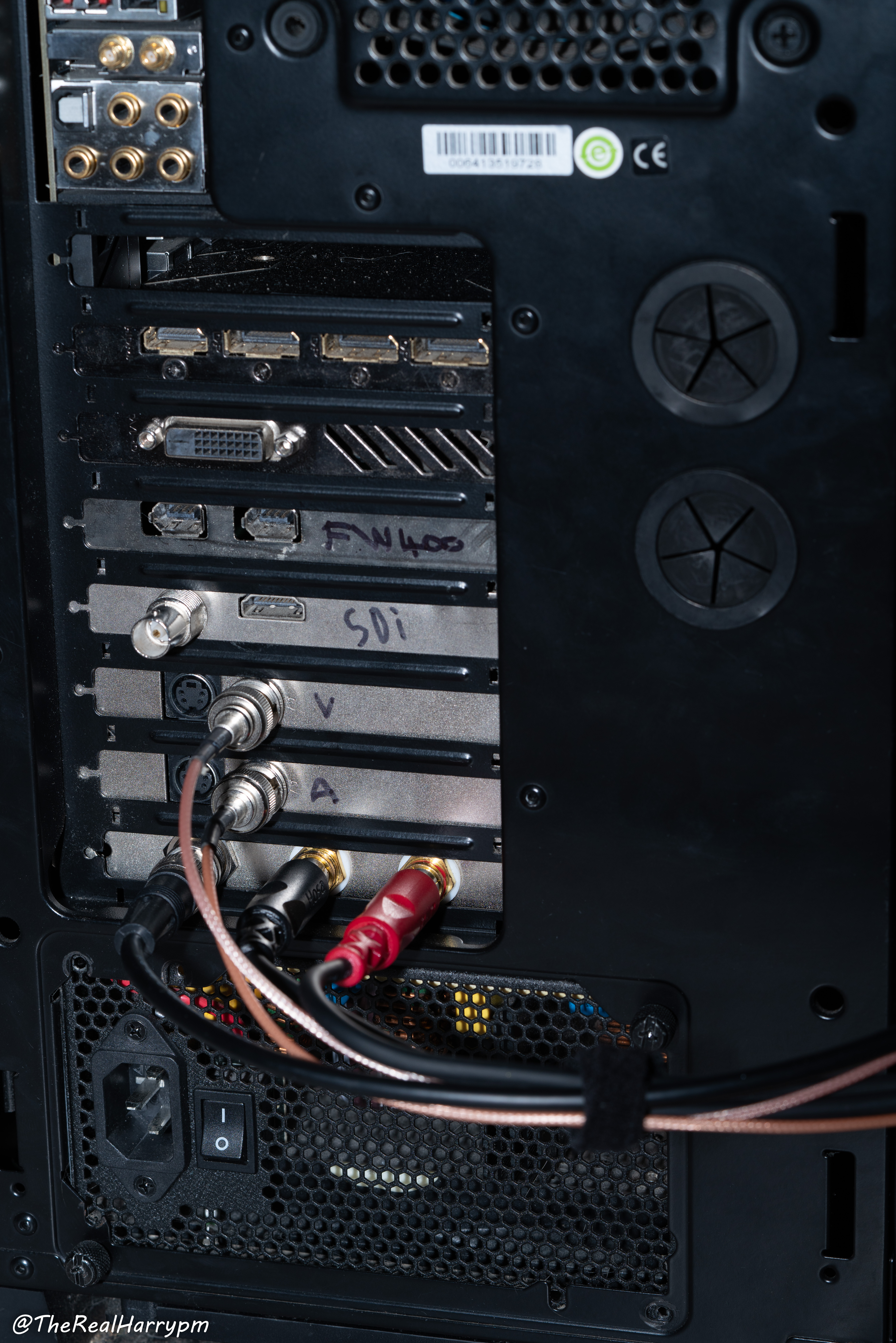
 # Connect your RF Capture Device & Capture!
> [!NOTE]
> RF Capture is not limited to the listed devices there is [other USB/PCIe/TB3 based SDRs](RF-Capture-Hardware).
> [!NOTE]
> There is a [Cables & Adaptors List/Guide](https://github.com/happycube/cxadc-linux3/wiki/What-Cables-To-Use)!
## CX Cards
For [CX Cards](CX-Cards) use the Luma Pin with an [S-Video](https://github.com/happycube/cxadc-linux3/wiki/What-Cables-To-Use) breakout cable for stock cards, Vmux1 via [BNC if modified](https://github.com/happycube/cxadc-linux3/wiki/Modifications#cx-card-modification).
# Connect your RF Capture Device & Capture!
> [!NOTE]
> RF Capture is not limited to the listed devices there is [other USB/PCIe/TB3 based SDRs](RF-Capture-Hardware).
> [!NOTE]
> There is a [Cables & Adaptors List/Guide](https://github.com/happycube/cxadc-linux3/wiki/What-Cables-To-Use)!
## CX Cards
For [CX Cards](CX-Cards) use the Luma Pin with an [S-Video](https://github.com/happycube/cxadc-linux3/wiki/What-Cables-To-Use) breakout cable for stock cards, Vmux1 via [BNC if modified](https://github.com/happycube/cxadc-linux3/wiki/Modifications#cx-card-modification).
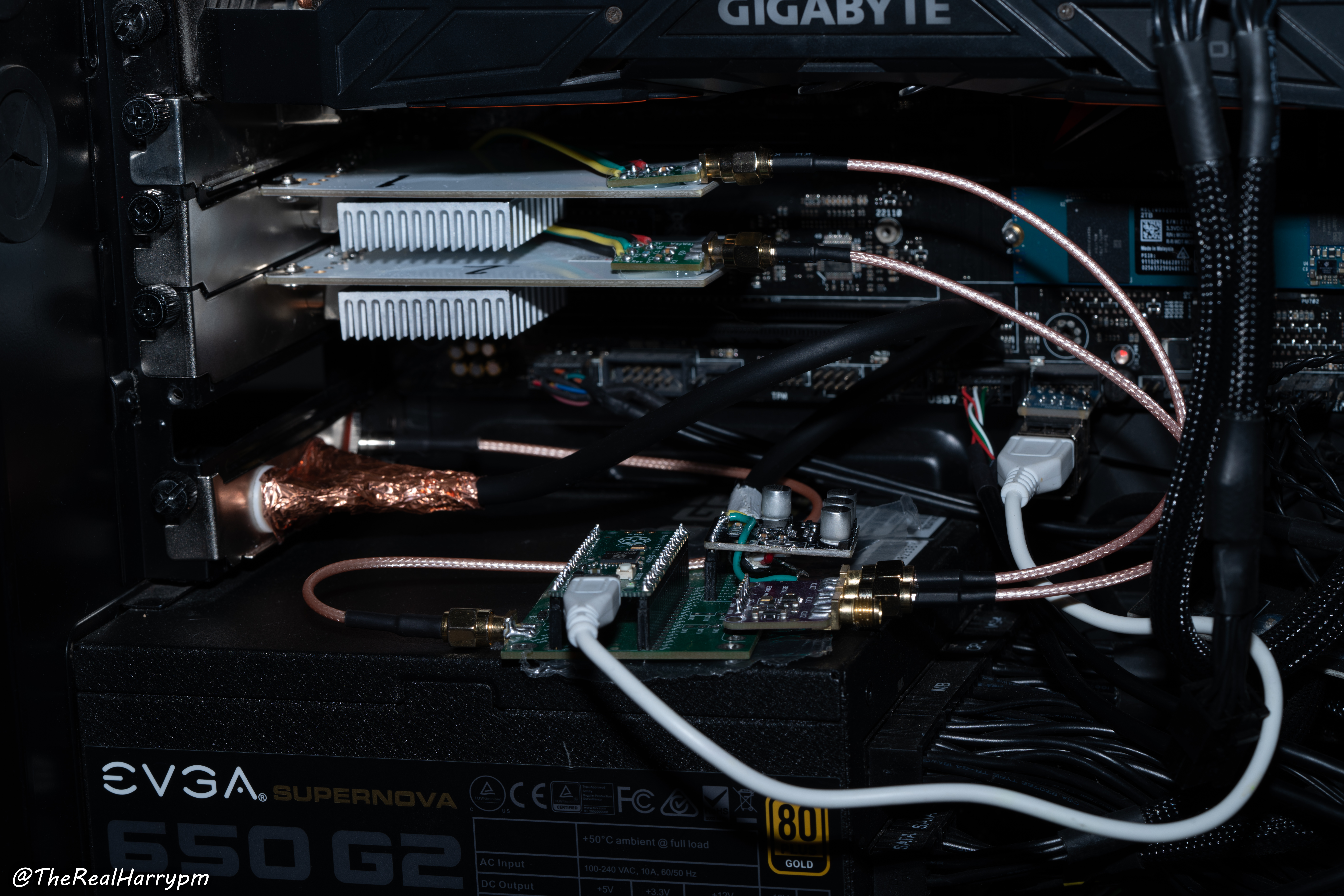
 ## Clockgen Mod
[Clockgen mod](Clockgen-Mod) has 2x CX Card with BNC Mod, C31 Mod, the 2 cards do Video RF + HiFi with an PCM1802 for Linear (or deck decoded HiFi audio) in sync capture.
## Clockgen Mod
[Clockgen mod](Clockgen-Mod) has 2x CX Card with BNC Mod, C31 Mod, the 2 cards do Video RF + HiFi with an PCM1802 for Linear (or deck decoded HiFi audio) in sync capture.
 ## DdD
Use 50Ohm BNC cables or a [direct coupler](https://s.click.aliexpress.com/e/_DBSsTZv) for the [Domesday Duplicator](https://github.com/happycube/ld-decode/wiki/Domesday-Duplicator).
## DdD
Use 50Ohm BNC cables or a [direct coupler](https://s.click.aliexpress.com/e/_DBSsTZv) for the [Domesday Duplicator](https://github.com/happycube/ld-decode/wiki/Domesday-Duplicator).
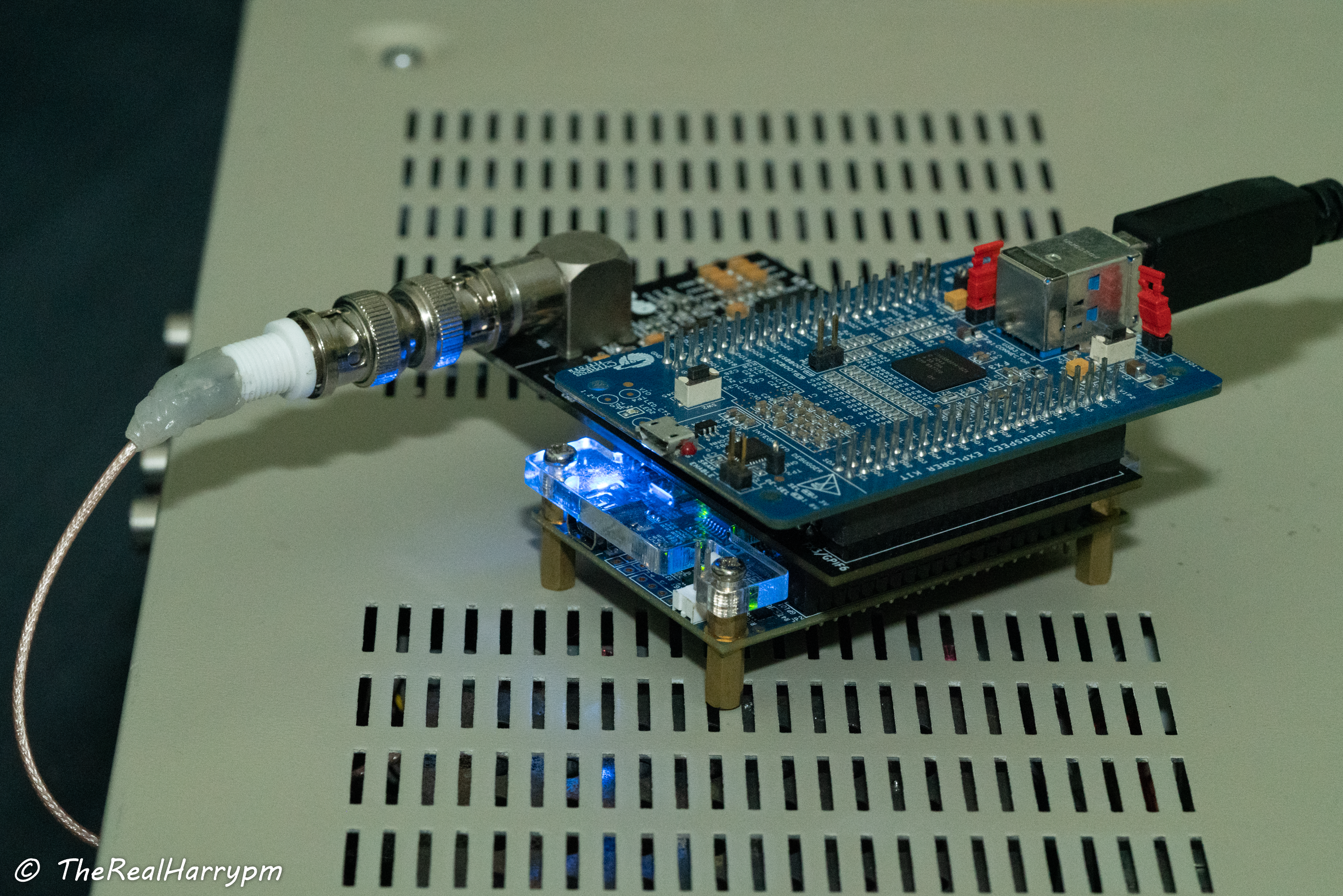 > [!CAUTION]
> The DdD should always have a shielded case and or be isolated from contact with the metal lids of VCRs.
# Page End
Next Page [The RF Capture Guide](RF-Capture-Guide)
Sub-Page [Troubleshooting Guide](Troubleshooting-Guide)
Sub-Page [RF Capture Hardware](RF-Capture-Hardware)
Previous Page [The Tap List](004-The-Tap-List)
> [!CAUTION]
> The DdD should always have a shielded case and or be isolated from contact with the metal lids of VCRs.
# Page End
Next Page [The RF Capture Guide](RF-Capture-Guide)
Sub-Page [Troubleshooting Guide](Troubleshooting-Guide)
Sub-Page [RF Capture Hardware](RF-Capture-Hardware)
Previous Page [The Tap List](004-The-Tap-List)