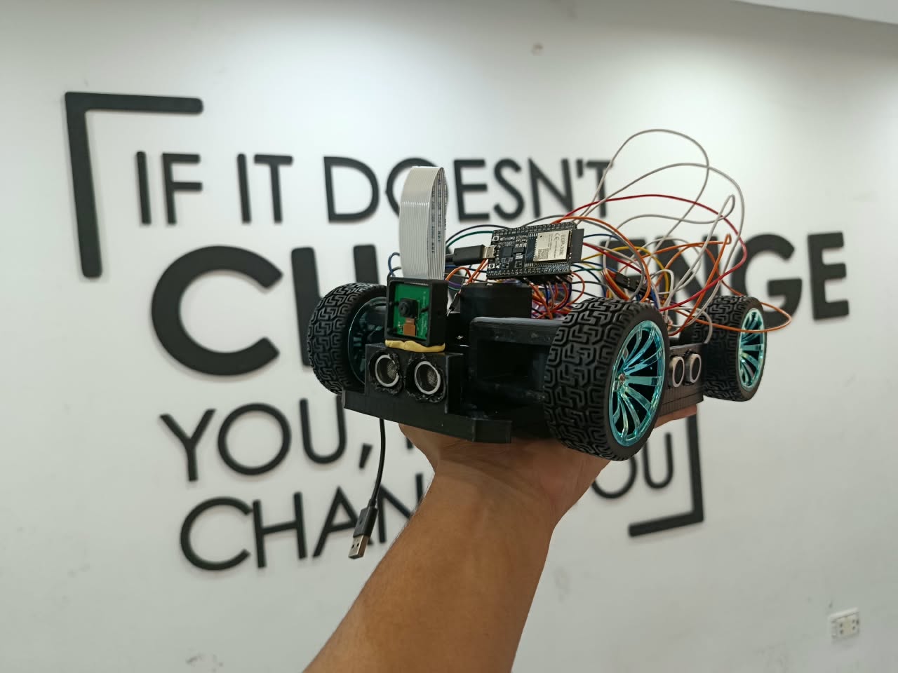
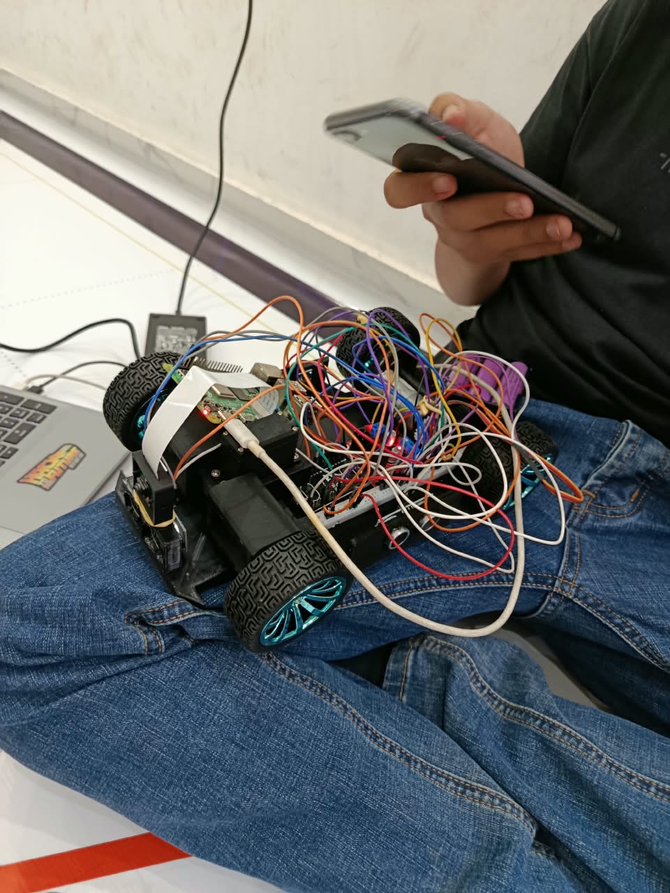
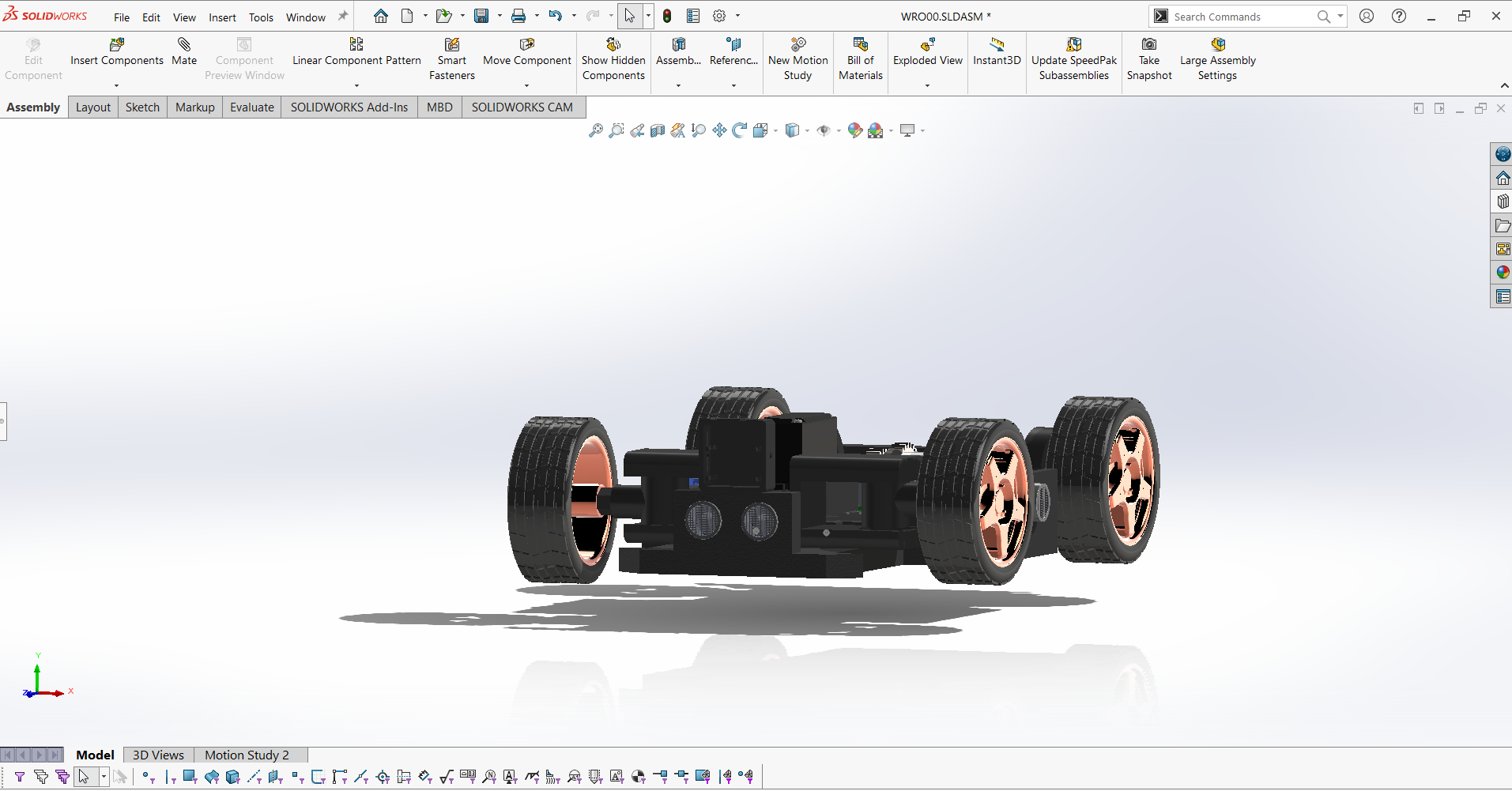
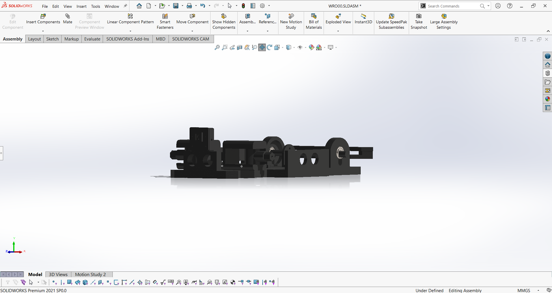
## 🏁 **WRO 2026 Future Engineers Challenges**
### **Two distinct autonomous navigation challenges testing vehicle intelligence and precision**
### **🚀 Open Challenge**
**Objective**: Complete three autonomous laps on dynamically configured tracks
| Aspect | Challenge | Our Solution |
|--------|-----------|--------------|
| **Track Variability** | Random internal wall placements | Adaptive path planning algorithms |
| **Navigation** | Unknown track layouts each round | Robust wall-following with corner detection |
| **Performance** | Consistent lap times across variations | Optimized PID control and sensor fusion |
| **Precision** | Maintain course in narrow lanes | High-accuracy steering and speed control |
### **🚧 Obstacle Challenge**
**Objective**: Navigate three laps with traffic sign compliance and precision parking
| Challenge Element | Requirement | Our Implementation |
|-------------------|-------------|-------------------|
| **Traffic Signs** | Red → Right bias
Green → Left bias | Real-time color detection with LAB colorspace |
| **Obstacle Avoidance** | Dynamic path adjustment | Smooth following at consistent distances |
| **Parking Maneuver** | Parallel parking after lap completion | Multi-stage parking with sensor validation |
| **Navigation** | Shortest path optimization | Efficient routing around obstacle combinations |
### **📁 Documentation Evaluation Framework**
## 📊 **WRO 2026 Engineering Documentation Scoring (30 points total)**
| Scoring Area | Maximum Points | Our Documentation Coverage |
|--------------|----------------|---------------------------|
| **1. Mobility Management** | 4 points | Complete mechanical design, motor selection, steering system, assembly instructions |
| **2. Power & Sense Management** | 4 points | Power systems, sensor integration, wiring diagrams, component specifications |
| **3. Obstacle Management** | 4 points | Navigation algorithms, parking strategies, source code with detailed comments |
| **4. Pictures – Team and Vehicle** | 4 points | Multi-angle vehicle photos, team photos, component labeling |
| **5. Performance Videos** | 4 points | Complete challenge demonstrations with commentary and analysis |
| **6. GitHub Utilization** | 4 points | Version control, structured documentation, regular commits |
| **7. Engineering Factor** | 4 points | Custom design and manufacturing throughout the vehicle |
| **8. Overall Judge Impression** | 2 points | Clear communication enabling easy replication |
| **Total Documentation Score** | **Still unknown (WE Haven't Competed Yet** | **(≈25% of total competition score)** |
### **Key Evaluation Areas**
- Still Unknown ( WE will Update all These Areas After The Competion )
**Scoring Philosophy**: Documentation is evaluated based on completeness, structure, and ease of replication - not comparison between teams. Each scoring area uses a 0-4 point scale where "Exceeds Expectations" requires not only enabling exact duplication but also providing improvement suggestions.
### **🎓 Educational Objectives**
- **Advanced Computer Vision**: Real-world implementation of color space theory
- **Sensor Fusion**: Integrating multiple data sources for robust navigation
- **Control Systems**: Precision steering and speed control algorithms
- **Engineering Documentation**: Professional technical communication
- **Problem Solving**: Systematic approach to technical challenges
---
## 🤖 **Our Robot**
| Component | Image | Quantity | Function | Key Specifications |
|-----------|-------|----------|----------|-------------------|
| **Raspberry Pi 4 Model B (4GB)** |

| 1 | Main Processing & Vision | Quad-core Cortex-A72, 4GB RAM, Peripheral & Camera Interface |
| **Raspberry Pi Camera Module 2 (8MP)** |
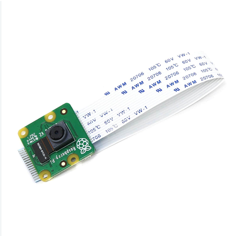
| 1 | Visual Navigation | 8MP Sony IMX219 sensor, 1080p video, CSI interface |
| **HC-SR04 Ultrasonic Sensor** |
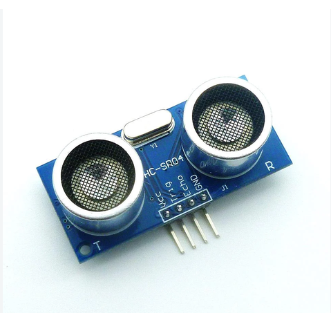
| 2 | Distance & Obstacle Detection | 2cm to 400cm range, 15-degree measurement angle |
| **MG966R Servo Motor** |
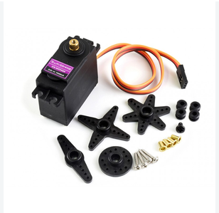
| 1 | Steering Actuation | High-torque metal gear servo, 180° rotation |
| **L298N Motor Driver** |
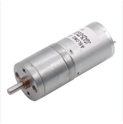
| 1 | Motor Control | Dual H-bridge driver, up to 2A current per channel |
| **LiPo Battery Pack** |
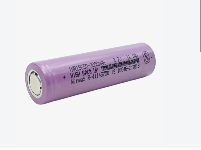
| 1 | Power Source | High-capacity rechargeable lithium polymer power supply |
**Component Selection Philosophy**: We prioritize widely available, well-documented components to ensure reproducibility. All parts can be sourced through standard electronics distributors using the provided specifications and images.
### **Professional Wiring Implementation**
1) Complete hand-drawn and digitally traced professional wiring schematic showing all electrical connections (view full resolution) • 2) Physical implementation demonstrating socket-based construction of the schematic
| Component Schematic | Description | Full Documentation |
| --- | --- | --- |
|

| **Raspberry Pi 4 Connection System**
GPIO interface, power distribution, and camera CSI connection | [View Details](schemes/README.md#microcontroller-systems) |
|

| **L298N Motor Driver Control**
PWM motor regulation and dual H-bridge connections | [View Details](schemes/README.md#motor-control-systems) |
|

| **MG966R Servo Control**
Steering mechanism PWM signal mapping | [View Details](schemes/README.md#motor-control-systems) |
|

| **HC-SR04 Ultrasonic Sensor Network**
Trigger and echo pin integration for distance measurement | [View Details](schemes/README.md#sensor-systems) |
|

| **Power Management & Distribution**
LiPo battery charging and main power regulation | [View Details](schemes/README.md#power-management-components) |
|

| **User Interface & Control**
Start push button and tactile system interface | [View Details](schemes/README.md#-interface--control-systems) |
### **Power Management Innovation**
During system integration, we identified a critical design limitation in our chosen power management IC. The LiPo Rider Plus's switch only controlled the 5V output rail, leaving the 3.3V regulator permanently active and creating potential battery drain.
**Engineering Solution**:
* **Root Cause Analysis**: Direct battery routing to auxiliary components bypassing the main control switch, causing minor standby current draw.
* **Component Modification**: Remapped power distribution lines and integrated a reliable master power distribution path.
* **Implementation**: Rerouted the main input rails through the primary hardware switch to ensure complete circuit isolation when deactivated.
* **Validation**: Full power cut-off achieved with zero standby current draw, protecting the Raspberry Pi and motor drivers from unwanted power leakage.
### **Signal Integrity Systems**
The **LM2569 Buck converter** ensures reliable communication between our 3.3V microcontrollers and 5V servo system. This implementation prevents signal degradation and ensures precise servo positioning under all operating conditions.
### **Thermal Performance Validation**
Comprehensive thermal analysis confirmed optimal operating temperatures across all critical subsystems:
### **Sensor Integration Challenges**
Our minimal vertical profile created unique challenges for Time-of-Flight sensor implementation. The proximity to ground plane caused premature ground intersection in the sensors' field of view, limiting effective detection range.
**Optical Solution**:
- **Angular Adjustment**: Upward sensor tilt to delay ground intersection
- **Optical Modification**: Custom window lenses to narrow field of view
- **Performance Improvement**: Extended usable detection range from ~150cm to ~300cm
### **Development Convenience Features**
Implementation of magnetic USB connectors for programming interfaces significantly improved development workflow efficiency, allowing rapid code iterations without physical connector wear.

Easy-access programming interface with magnetic connection system
### **Performance Specifications**
- **Maximum Theoretical Speed**: 1.52 m/s (calculated from motor RPM and drive train ratios)
- **Operational Speed**: 1.4 m/s (PWM controlled for stability optimization)
- **Battery Endurance**: 3-4 hours typical operation
- **Charge Duration**: ~60 minutes via USB-C fast charging
- **Power Consumption**: 0.8W minimum, 200-250mA typical operational current
### Powertrain – Potential Improvements
- Switch to higher RPM coreless motor + greater 25:1 Micro Metal Gearbox → theoretical top speed > 2.3 m/s while keeping the same design.
- Replace the 25:25 external gear with an internal planetary stage inside the JGA27-370 motor can → saves 4 mm length with direct mounting of the motor to the rear axle.
- Active cooling (micro 10 mm fan, 0.8 g) → could improve the overall airflow in the system, allowing for faster operation and even higher stability.
---
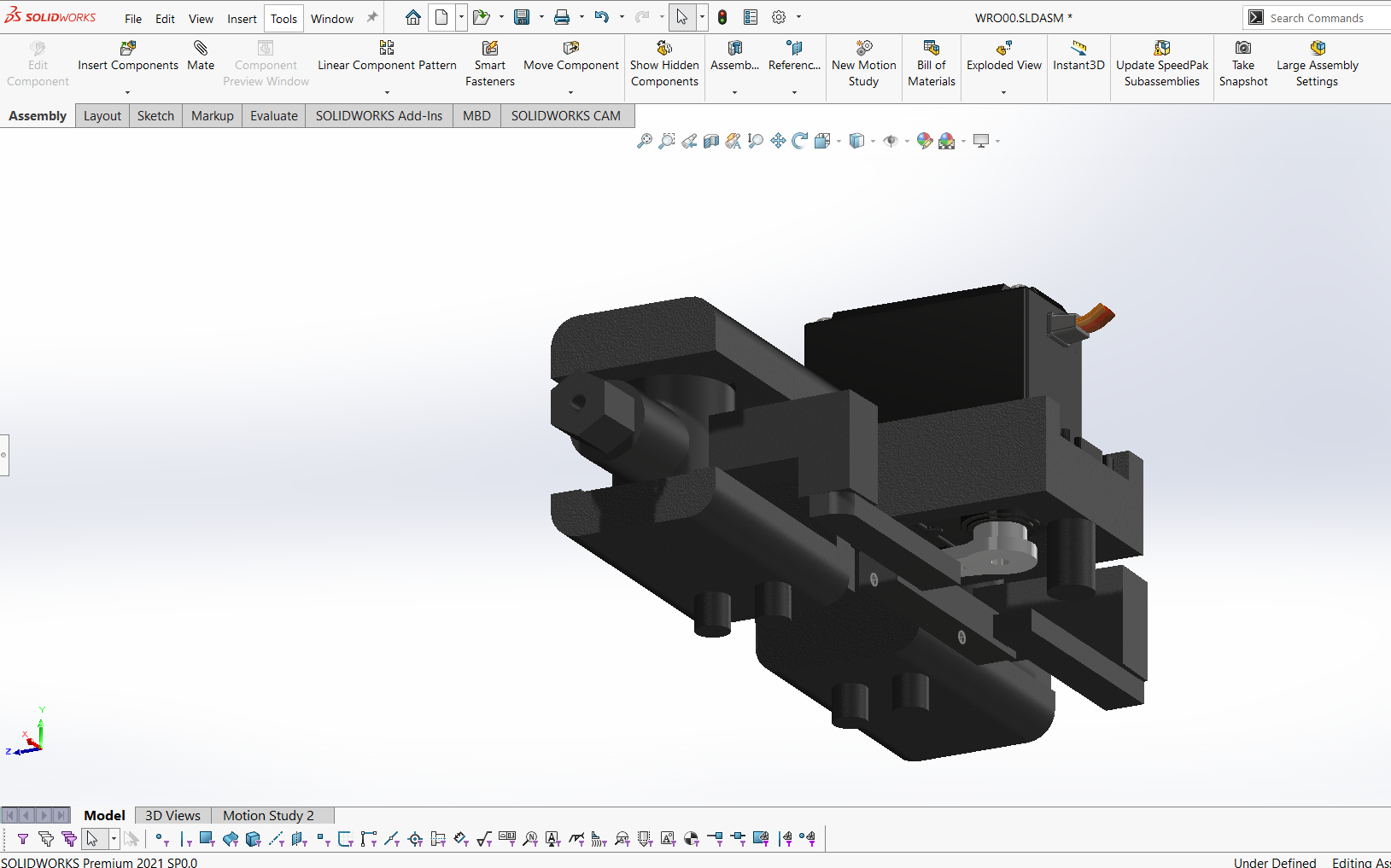
## ⚙ **Mechanical Systems**
Our mechanical design philosophy centers on achieving maximum capability within minimal dimensions through innovative engineering and precision manufacturing.
### **Core Mechanical Specifications**
- **Overall Dimensions**: 250mm (L) × 180mm (W) × 70mm (H)
- **Total Mass**: Approximately 800 grams
- **Structural Material**: 3D-printed PLA+ for optimal strength-to-weight ratio
- **Drive Configuration**: Rear-wheel drive with custom differential
- **Steering System**: True Ackermann geometry with precision linkage
### **Design Integration Approach**
Digital design precision translated to physical implementation through advanced manufacturing techniques
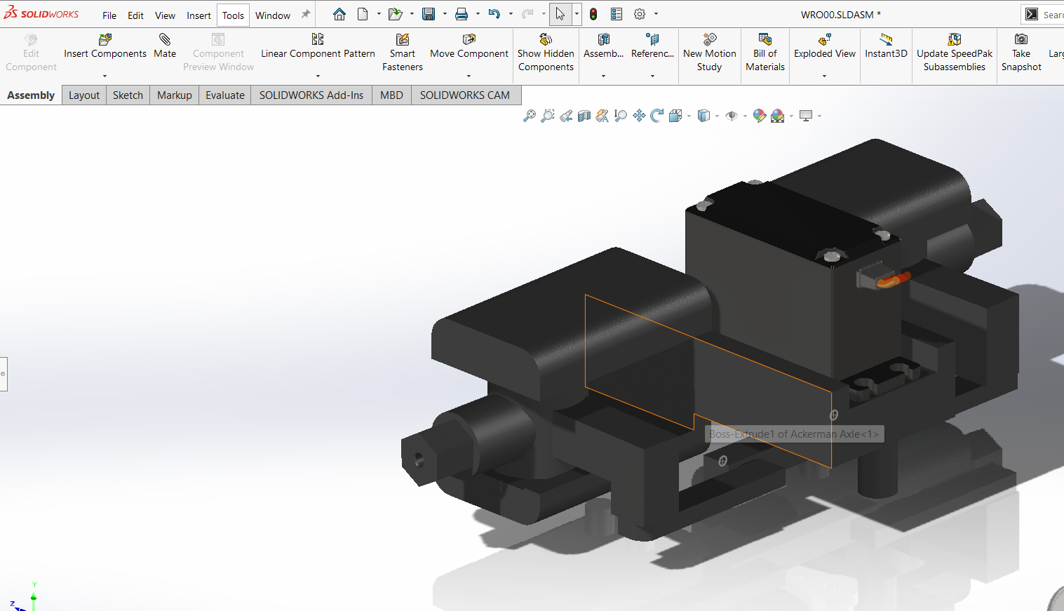
### **Steering Geometry Implementation**
Our custom Ackermann steering system ensures each wheel maintains optimal alignment during turns, minimizing tire scrub and maximizing maneuverability.
Dynamic steering simulation and geometric analysis ensuring optimal turning performance
**Steering System Evolution**:
- **Initial Concept**: Integrated print-in-place mechanism for rapid prototyping
- **Performance Refinement**: Multi-component assembly for long-term precision
- **Final Implementation**: Four M2 fasteners with locking nuts for permanent alignment
- **Wheel Articulation**: -50° to +32° range optimized for competition track dimensions
### Mechanical – Potential Improvements
- True Ackermann geometry.
- Ball bearings on the two rear wheels → theoretical 7–9 % less rolling resistance in CAD tests.
- Possible uspension system using micro torsion bars could improve stability if the track includes ground obstacles in the future when crossing the 3 mm track.
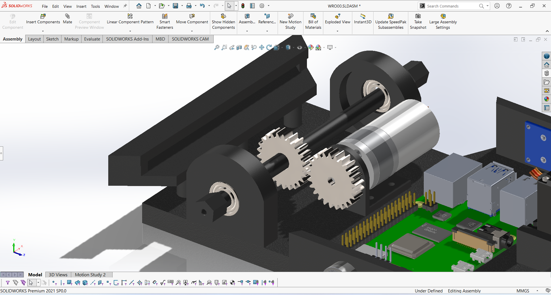
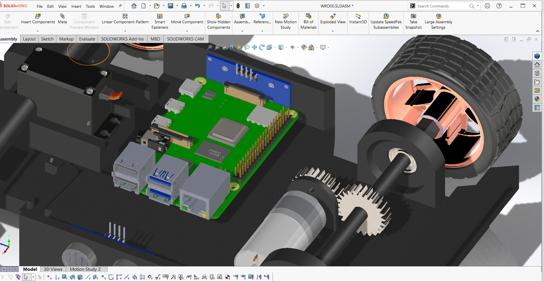
### **Power Transmission System**
The custom 2-gear differential ensures smooth torque distribution during turning maneuvers, preventing wheel slip and maintaining traction.
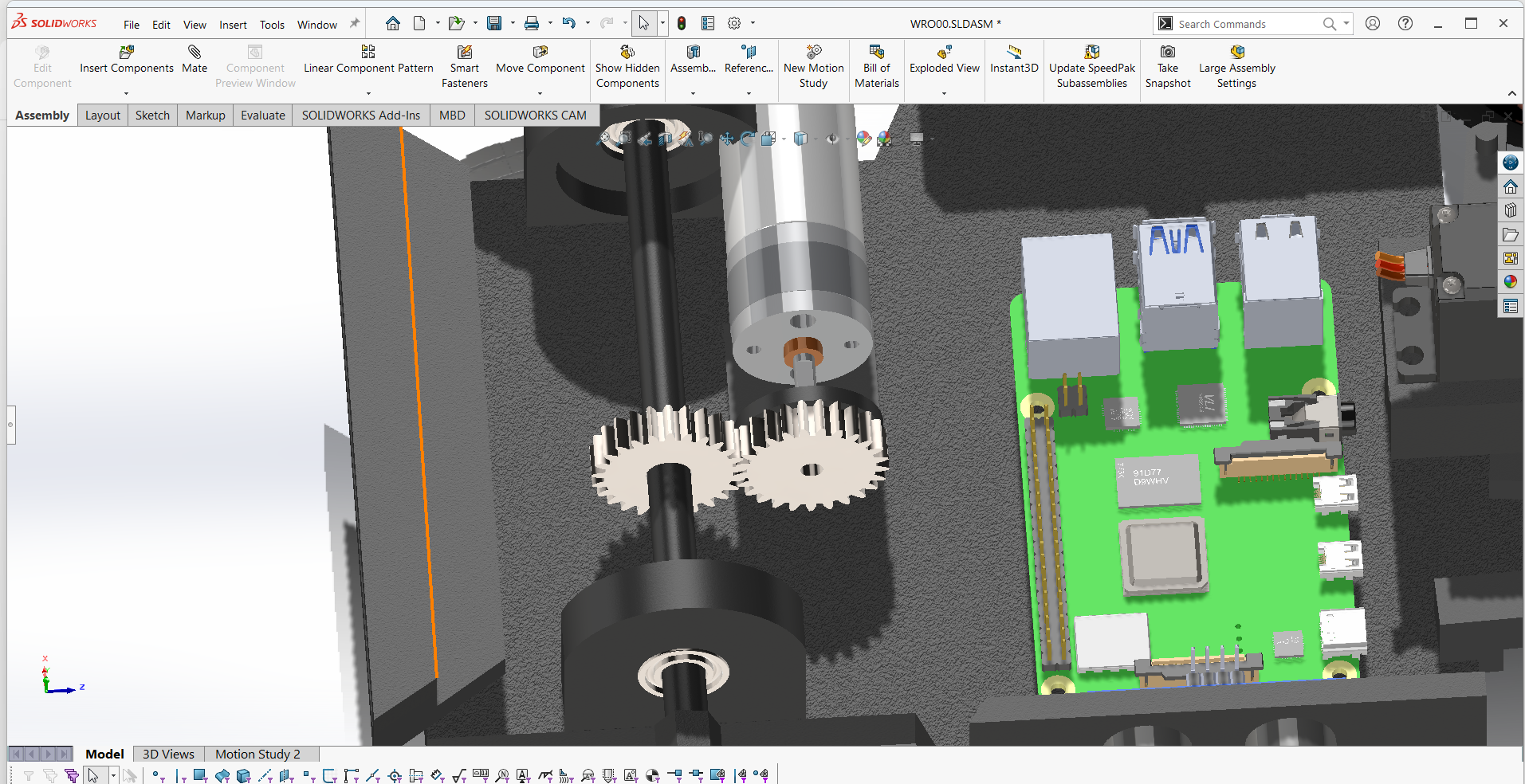
Physical validation of drive transmission operation and comprehensive CAD documentation
**Gear System Architecture**:
- **Speed Reduction**: 25:25 ratio through custom spur gear design
- **Torque Distribution**: Two 25-tooth spur gears enabling independent wheel rotation transferring the torque direct from the motor.
- **Manufacturing Precision**: 100% infill for maximum durability under load
- **Efficiency Optimization**: Precisely calculated tooth profiles for minimal power loss
### **Manufacturing File Repository**
*All components provided in 3MF format for maximum compatibility across different 3D printing platforms and slicing software*
| Component | File Reference | Quantity | Visual Reference | Functional Description |
|-----------|----------------|----------|------------------|------------------------|
| **Main Chassis** | [`RCBC Chassis.3MF`](Mechanical_Design/RCBC%20Chassis.3MF) | 1 |
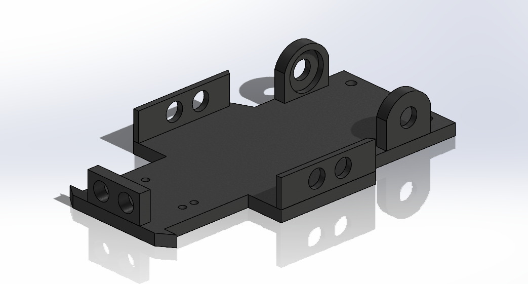
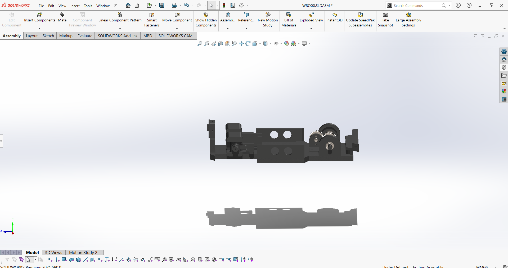
| Primary structural element with integrated mounting features |
| **Motor Bracket** | [`JGA25-370 motor bracket.step.3MF`](Mechanical_Design/JGA25-370%20motor%20bracket.step.3MF) | 1 |
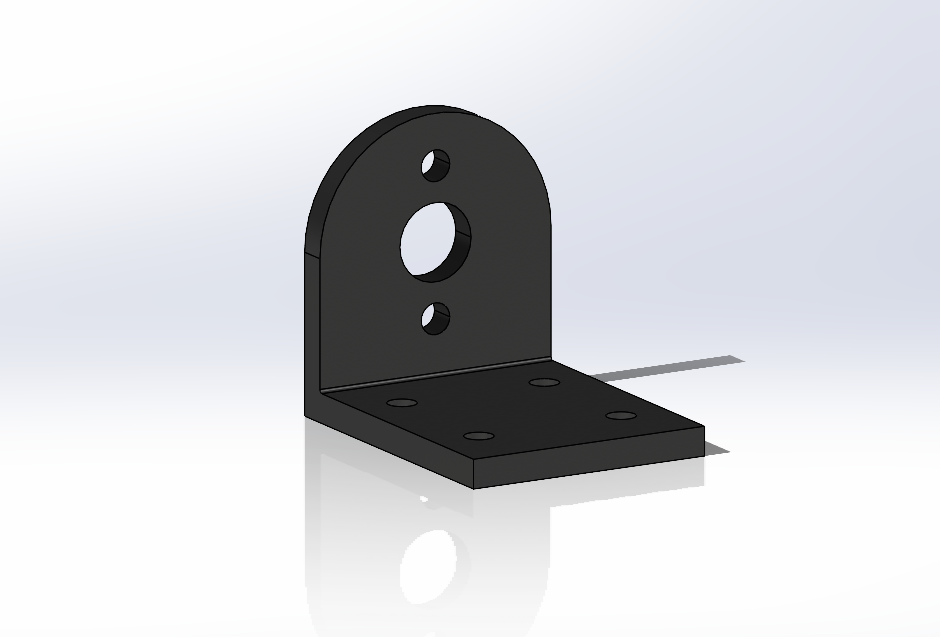
| Mounting bracket specifically designed for JGA25-370 motor |
| **Ackerman Axle** | [`Ackerman Axle.3MF`](Mechanical_Design/Ackerman%20Axle.3MF) | 1 |
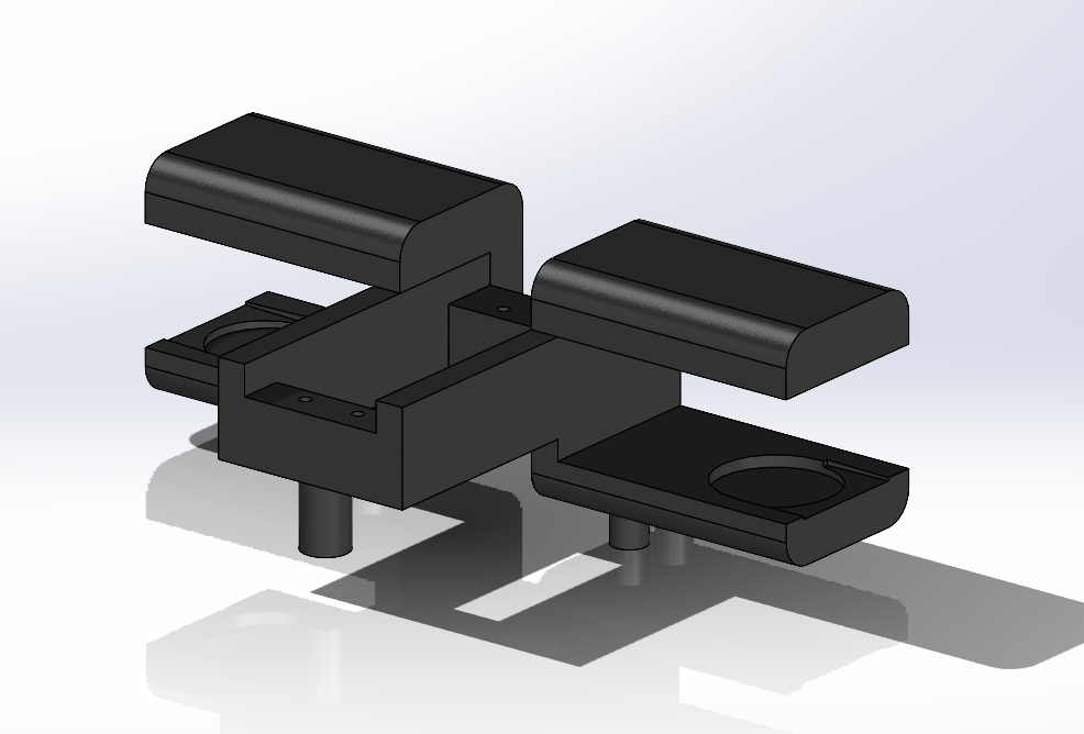
| Main steering linkage for Ackermann geometry |
| **Knuckle Joint** | [`Knuckle_Joint_boze.3MF`](Mechanical_Design/Knuckle_Joint_boze.3MF) | 2 |
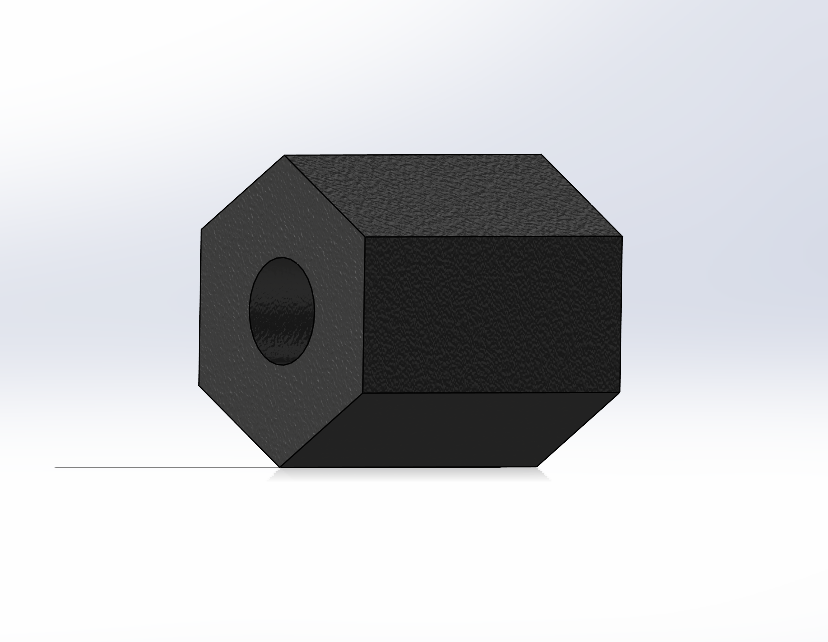
| Steering knuckle joints for front wheels |
| **Rotation Left** | [`Rotation_Left.3MF`](Mechanical_Design/Rotation_Left.3MF) | 1 |
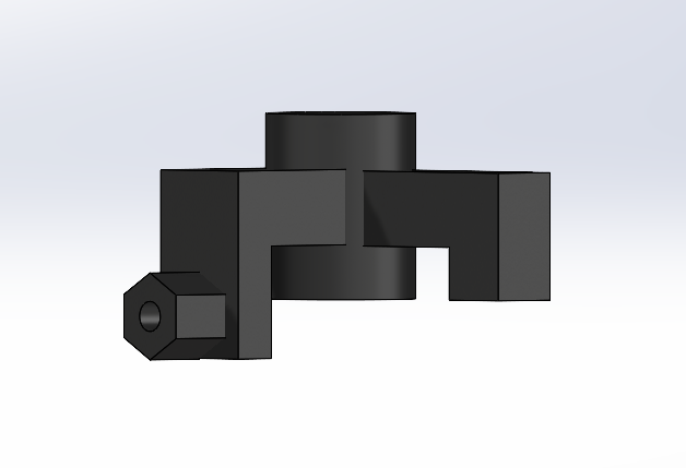
| Left side steering rotation component |
| **Rotation Right**| [`Rotation_Right.3MF`](Mechanical_Design/Rotation_Right.3MF) | 1 |
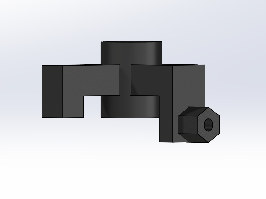
| Right side steering rotation component |
| **Servo Connector** | [`Servo_Connector.3MF`](Mechanical_Design/Servo_Connector.3MF) | 1 |
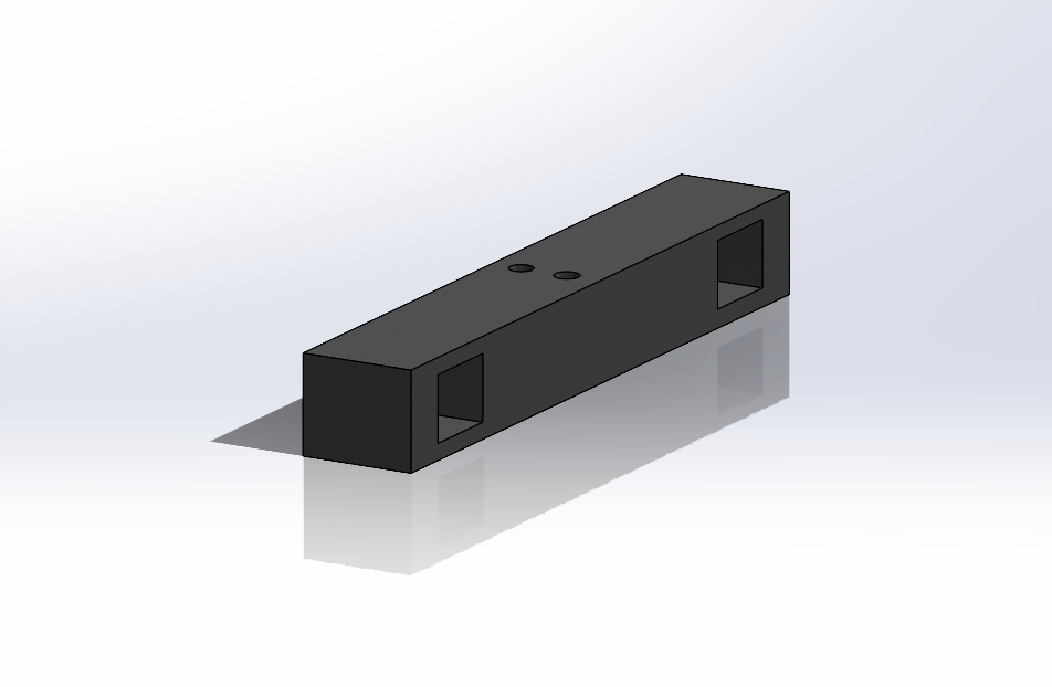
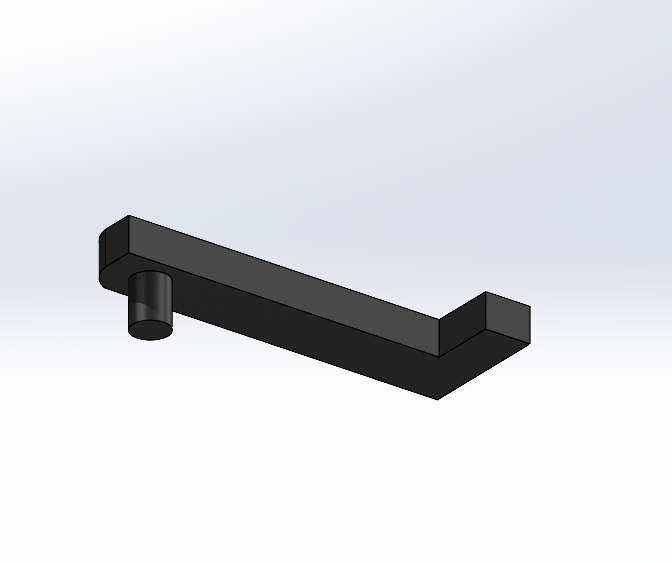
| Linkage connecting the steering servo to the axle |
| **Spur Gear** | [`spur gear_am.3MF`](Mechanical_Design/spur%20gear_am.3MF) | 1 |
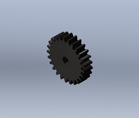
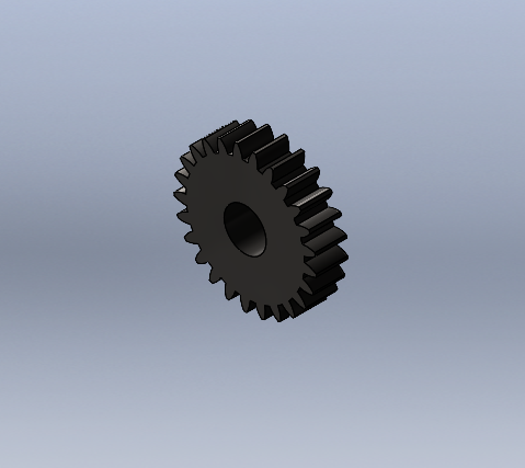
| Main torque transmission spur gear |
| **Drive Shaft** | [`Shaft.3MF`](Mechanical_Design/Shaft.3MF) | 1 |
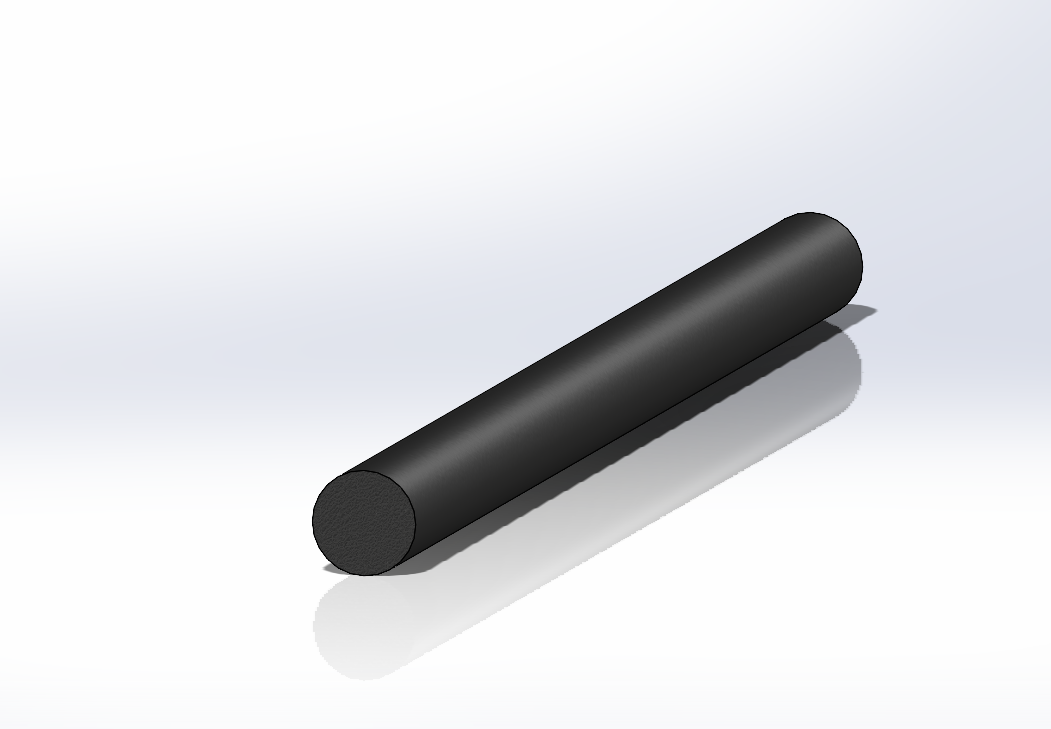
| Main mechanical drive transmission shaft |
| **Camera Casing** | [`camera casing 1.3MF`](Mechanical_Design/camera%20casing%201.3MF) | 1 |
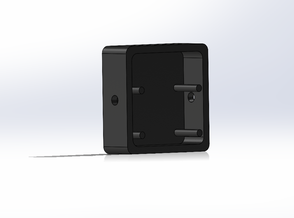
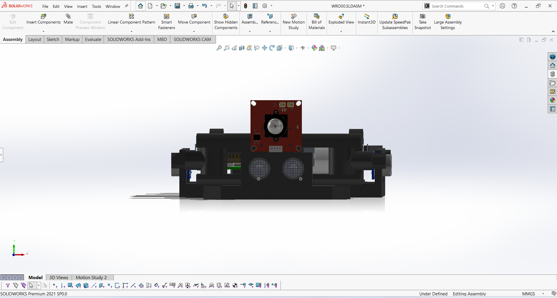
| Enclosure and protection for the vision system |
| **Rear Spoiler** | [`spoiler.3MF`](Mechanical_Design/spoiler.3MF) | 1 |
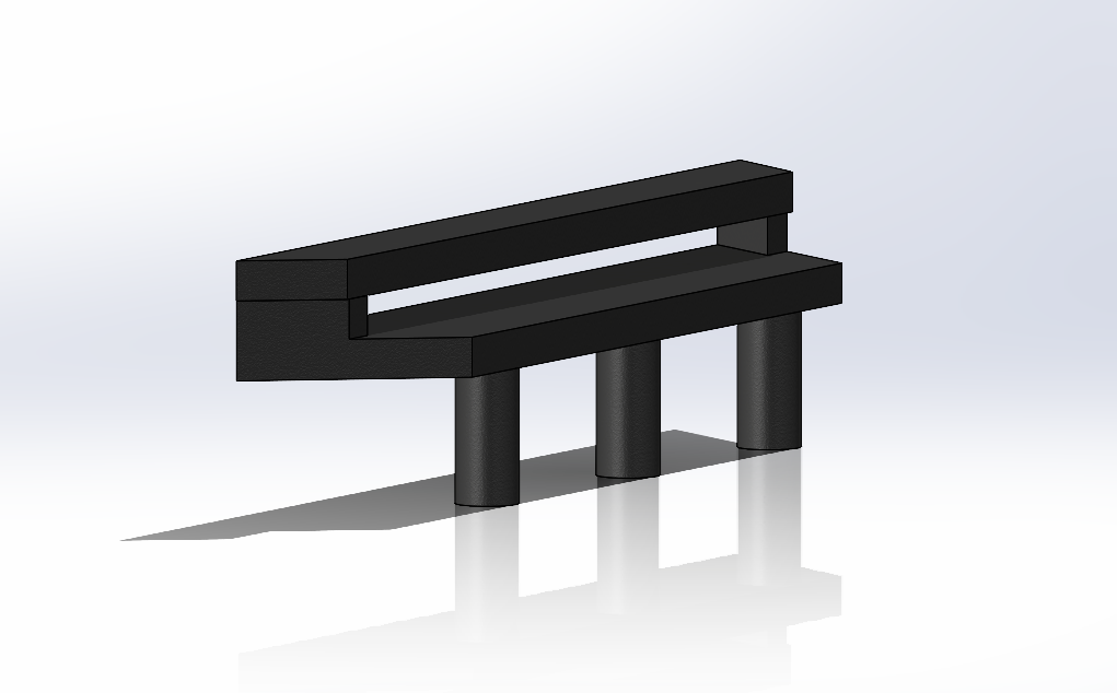
| Aerodynamic rear spoiler structure |
### **Performance Engineering Analysis**
**Drive Train Calculations**:
- **Motor Specification**: 450 RPM JGA 25-370 DC motor with quadrature encoder
- **Gear Reduction**: 25:25 ratio providing optimal speed-torque balance
- **Theoretical Maximum Velocity**: 1.52 m/s derived from wheel geometry and drive ratios
- **Operational Velocity**: 1.5 m/s selected for optimal control stability
**Structural Analysis**:
- **Motor Torque Capacity**: ~1.25 Nm at 12V, sufficient for 800g vehicle acceleration
- **Bearing System**: Two precision bearings minimizing rotational friction
- **Steering Load Management**: Mechanism optimized for servo torque characteristics
- **Impact Resistance**: Validated through comprehensive testing under competition conditions
### **Assembly Methodology**
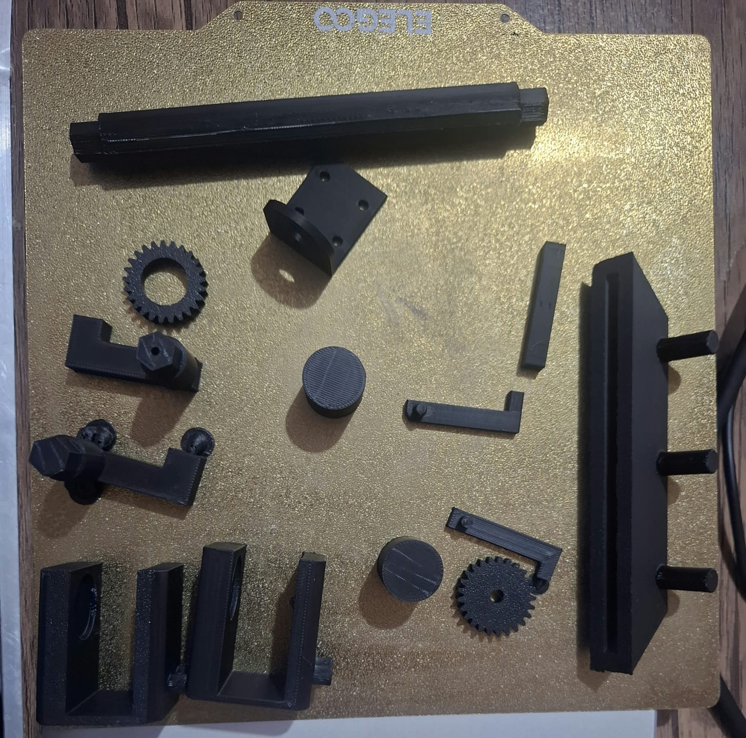
Staged assembly approach ensuring proper system integration and alignment
**Assembly Sequence**:
1. **Drive System Integration**: Differential assembly and motor mounting with M3 hardware
2. **Steering Mechanism Installation**: Ackermann linkage and servo integration
3. **Wheel System Assembly**: Bearing installation and wheel mounting
4. **Electronic System Integration**: Bread board installation and component connection
5. **Final System Validation**: Comprehensive functional testing and alignment verification
---
## 💻 **Software Architecture**
Our software implementation employs a distributed processing architecture that optimizes performance through specialized task allocation between multiple processors.
### **System Architecture Overview**
|
**Processing Distribution**:
- **Vision Processing Unit**: Raspberry Pi 4 handling real-time image analysis and high-level decision making
- **Sensor Fusion Unit**: esp32 managing multi-sensor data acquisition and preprocessing
- **Communication Bridge**: Bidirectional UART protocol at 115200 baud for inter-processor data exchange
**Core Software Components**:
- [`vision_source.py`](src/open.py) - Open challenge navigation algorithms and obstacle challenge with integrated parking
- [`calibration.py`](src/obstacle.py) - calibration for the different variables
- [`esp32_car.ino`](src/uart_slave.ino) - Sensor and motor management firmware
|
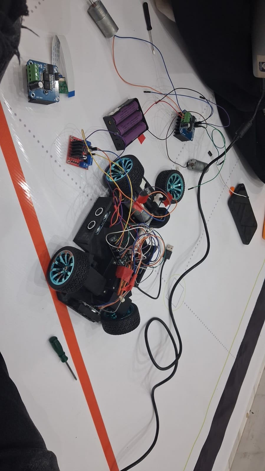
Integrated development and testing setup
|
### 📄 **Development Environment & Code Deployment**
#### **Raspberry Pi 4 Model B (Camera Microcontroller)**
- **Programming Language**: Python 3 for rapid development and testing
- **Development Interface**: Direct micro USB / HDMI connection to Raspberry Pi with a live OpenCV debug window (`cv.imshow`)
- **Core Libraries**:
- `opencv-python (cv2)` - Image preprocessing, HSV color masking, and contour-based object detection
- `numpy` - Array operations for HSV bounds and morphological kernels
- `pyserial` - UART serial communication with the ESP32 microcontroller
#### **esp32 (Sensor and Motor Microcontroller)**
- **Programming Language**: Arduino C++ for efficient sensor and motor data handling
- **Development Interface**: Standard micro USB connection to evaluation board
- **Essential Libraries**:
- `ESP32Servo.h` - PWM-based control of the steering servo
- **Communication Protocol**: UART Serial (115200 baud) between the Raspberry Pi and ESP32, used to relay vision-based obstacle data (color, distance, position)
#### **Development Workflow Optimization**
We implemented magnetic USB connectors for the camera microcontroller, providing significant advantages during intensive development cycles. The magnetic interface enables rapid connection changes, prevents physical port damage from repeated use, and streamlines the programming and debugging process.
#### **Code Deployment Process**
1. **Raspberry Pi 4 Model B Python Deployment**:
- Transfer `.py` source files directly to microcontroller filesystem using magnetic USB connection
- Automatic execution initialization from `vision_source.py` on system startup
- Adding the calibration code in order to adjust the variables
- No compilation overhead - immediate interpreted execution for rapid iteration
2. **esp32 Arduino Deployment**:
- Compile source code in Arduino IDE with ESP32 board package support
- Upload compiled binary via micro USB interface to evaluation board
- Precompiled firmware deployment ensuring reliable sensor and motor operation
### 🎨 **Vision Processing Strategy**
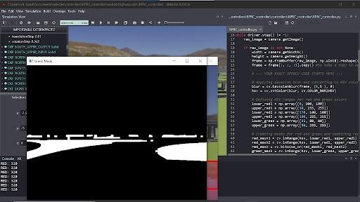
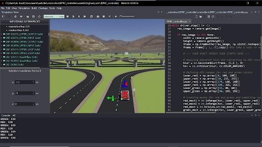
We selected the **HSV color space** for its superior performance under variable lighting conditions compared to traditional RGB representation. Detection thresholds for the red and green obstacle pillars, as well as the white track floor, were manually calibrated and fine-tuned per venue using a dedicated debug mask window.
**Technical Rationale**: HSV colorspace provides adequate performance for our application requirements, isolating hue independently from brightness/lighting variance, while more complex approaches (e.g. machine learning-based detection) would introduce unnecessary computational overhead without significant benefits for this specific use case.
**Calibration Debug Windows**:
## 📸 **Testing & Calibration Visuals**
### **Detection Code Testing**
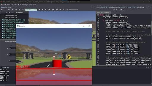
### **Calibration Testing**
### 🧭 **Navigation Algorithm Implementation**
#### **Obstacle Challenge Navigation**
**State Machine Flow**:
Vision Obstacle Avoidance → Clearance → Corner Turn → Wall Following (repeat)
↑ ↑ ↑ ↑
Camera Color Post-Obstacle Ultrasonic Ultrasonic
Detection (R/G) Stabilizing Front Distance Left/Right PID
**Navigation Pseudocode**:
INITIALIZE sensors, center steering, stop motor
LOOP:
READ ultrasonic distances (front, left, right)
READ vision data from camera (color, distance, x-position)
IF obstacle color == RED and distance within range:
STEER hard RIGHT, drive at obstacle speed
CONTINUE to next loop
IF obstacle color == GREEN and distance within range:
STEER hard LEFT, drive at obstacle speed
CONTINUE to next loop
IF recently cleared an obstacle (within clearance window):
CENTER steering, drive at clearance speed
CONTINUE to next loop
IF currently turning a corner:
CONTINUE steering toward corner direction
IF front distance becomes clear OR max corner time exceeded:
END corner, center steering
CONTINUE to next loop
IF front distance
**Color-Specific Behaviors**:
- **Red Object Detection**: Right-side bias navigation with maintained offset
- **Green Object Detection**: Left-side bias navigation with maintained offset
- **Position Maintenance**: Consistent pixel positioning for smooth obstacle tracking
## 📸 **Testing & Calibration Visuals**
### **Red Color Detection**
### **Sensor and motor Fusion Implementation**
**Data Integration Pipeline**:
```
esp32 Sensors ←→ UART ←→ Raspberry Pi 4 Model B → Sensor Fusion → Control Decisions
↑ ↑ ↑ ↓
Ultrasonic Left Camera PID Controller Motor/Servo
Ultrasonic Right Vision State Machine Actuators
Ultrasonic Front
Encoder Data
```
### **Control System Implementation**
**Steering Control Algorithm**:
```python
# Proportional controller implementation for smooth navigation
def calculate_steering_correction(target_cx, frame_center_x):
error = target_cx - frame_center_x
steering_angle = error * KP_GAIN
steering_angle = clamp(steering_angle, -0.5, 0.5)
return steering_angle
```
### **Inter-Processor Communication**
**UART Protocol Specification**:
- **Baud Rate**: 115200 for reliable data throughput
- **Command Structure**: Comma-separated plain-text messages terminated by newline
- **Data Validation**: Field-count check (color, distance, x-position) before parsing
- **Error Recovery**: Timeout-based fallback - if no valid message is received within the timeout window, the obstacle state automatically resets to "none detected"
**Master (Raspberry Pi 4) → Slave (ESP32) Messages**:
- `R,
,` - Red obstacle detected: distance in cm, horizontal pixel position
- `G,,` - Green obstacle detected: distance in cm, horizontal pixel position
- `N` - No obstacle currently detected
**Slave Response Formats**:
- **All sensors**: `left_distance,right_distance,encoder_distance\n`
- **Left Ultrasonic only**: `left_distance\n`
- **Right Ultrasonic only**: `right_distance\n`
- **Encoder only**: `encoder_distance\n`
### **Parking Maneuver Analysis**
Our compact dimensions required innovative parking strategies to operate within the constrained parking space.
### **Parallel Parking Strategy Optimization**
**🚧 Challenge**: Our compact vehicle length required extremely precise maneuvers.
- **Critical Clearance Design**: Narrow extension width allowed wall clearance during turns
- **🔄 Maneuverability Enhancement**: Additional space enabled reliable parking execution
**Multi-Stage Parking Sequence**:
1. **Approach Phase**: Follow magenta wall using camera guidance
2. **Turn-in Execution**: 80-degree turn outside parking spot
3. **Alignment Phase**: Odometry-based reverse positioning
4. **Reverse Maneuver**: Controlled backing for final alignment
5. **Straighten Phase**: Final orientation adjustment
### Parallel Parking – Potential Improvements
- Pure vision-based parking using parking walls as obstacles → eliminates Ultrassonic distance dependency and works even if the parking zone is shifted elsewhere.
- Single-motion slow parking trajectory instead of safer fast three-segment → would save ~1.5 s .
### **Obstacle Navigation Patterns**
The algorithm handles all possible obstacle combinations through systematic pattern recognition and response.
### **Vision Processing Pipeline**
1. **Image Capture**: 320×240 resolution at 26 frames per second
2. **Color Transformation**: RGB to LAB colorspace conversion
3. **Feature Detection**: Blob analysis with size and shape filtering
4. **Target Identification**: Largest valid blob selection for reliability
5. **Error Calculation**: Position deviation from desired tracking point
### **Software & Algorithms – Potential Improvements**
- Replace hand-tuned proportional-only steering with a full PID controller → would reduce oscillation and improve response to sudden error changes, especially during obstacle avoidance.
- Add IMU-based heading correction (e.g. MPU6050 on the ESP32) as a backup when ultrasonic wall readings are lost or unreliable, instead of relying on ultrasonic distance alone for cornering.
- Auto-calibrate HSV thresholds at startup using a reference color card, reducing the need for manual venue-specific tuning of the lane/red/green masks.
- Enable bidirectional UART communication → let the ESP32 report back sensor data (front/left/right distances) to the Raspberry Pi, allowing more informed vision-based decisions instead of one-way commands.
Complete software implementation details available in our [source code documentation](software/README.md).
---
## 📹 **Performance Videos**
Our development process included precise testing and validation to ensure competition-ready performance across both challenge scenarios.
### **Competition Performance**
- **Open Challenge**: 16-second perfect score demonstration
- **Obstacle Challenge**: 35-second perfect score with integrated parking
- **Detection Reliability**: >95% accuracy across variable lighting conditions
- **System Responsiveness**: <50ms latency from detection to actuation
### **Video Documentation**
Complete performance demonstrations showcasing our vehicle's capabilities:
📹 **Full video library**: [Google Drive - Performance & Testing Videos](https://drive.google.com/drive/folders/1aqdMkAl4uZPi23gUwCWyC1Bx4tsVxPQt)
Selected highlight clips are also available directly in this repository under [`Videos/`](Videos/).
**Media Production**: All logos and visual media edits were created by our team using the ***ibisPaint X*** mobile application. Video overlay commentary and caption explanation edits were also done by our team using ***CapCut*** for professional presentation of our performance videos.
---
## 🌐 **GitHub Utilization & Development**
GitHub served as the central platform for project management, version control, and public documentation. To ensure a well-organized and professional repository, we followed a milestone-based development workflow. Development and testing were conducted locally, with updates committed and documented after the completion of major engineering milestones, such as chassis finalization, sensor integration, and deployment of the core algorithms. This approach maintained a clear, structured, and easily traceable project history for both the development team and the wider community.
### **Development Workflow Strategy**
**Structured Development Approach**:
- **Local Development Environment**: Focused development work carried out on local machines using feature branches
- **Milestone-Based Committing**: Deliberate commits made at key points marking meaningful technical progress
- **Quality Assurance**: Careful testing and documentation completed before pushing updates to the public repository
- **Clean Public History**: A well-organized repository that reflects a polished and professional development journey
**File Sharing and Public Updates**: To keep our work accessible and easy for others to reproduce, all project assets — including CAD files (`models/`), electrical schematics (`schemes/`), and source code (`src/`) — are published publicly at every major milestone. Prior to each release, we carefully organize and clean up our code, data, and documentation to maintain a structured, easy-to-navigate repository. To support full transparency and proper version tracking, the exact date and time of each update is clearly noted in our README files.
### **Commit History & Project Evolution**
Our development timeline from June to september 2026 demonstrates consistent progress and systematic engineering:
**Key Development Milestones**:
- **July 2026**: Core mechanical design and electronic system implementation
- **August 2026**: Repository initialization and project structure establishment
- **August 2026**: national competition preparation and system optimization
**Commit Philosophy**: Each of our 20+ commits represents substantial technical progress, including:
- Complete mechanical system implementations (`design_base.3mf`, `4_gear_differential.3mf`)
- Electronic schematic and wiring documentation (`wiring_diagram.jpg`)
- Software algorithm development and optimization (`open.py`, `obstacle.py`)
- Comprehensive technical documentation updates across all 8 specialized folders
- Performance validation and testing results with competition videos
### **Repository Organization Excellence**
**Comprehensive Documentation Structure**:
- **8 Specialized Folders**: Each containing detailed technical README documentation
- **Structured File Organization**: Logical grouping of related technical assets
- **Professional Presentation**: Clean, well-organized repository layout
- **Easy Navigation**: Intuitive structure for both technical judges and future developers
### **Supporting Future Development & Replication**
## 🔧 **EASY REPLICATION & FUTURE DEVELOPMENT**
### **Our documentation enables effortless duplication by other teams and developers**
**Replication-Focused Design**:
- **Complete Bill of Materials**: All components clearly specified with datasheet information
- **Step-by-Step Assembly Guides**: Detailed instructions for mechanical and electronic assembly
- **Manufacturing Files**: 3MF format for universal 3D printing compatibility
- **Source Code Availability**: Complete software implementation with detailed comments and explanations
- **Troubleshooting Guidance**: Solutions to common implementation challenges
**Supporting Others and Future Development**: We're happy to see others learn from what we've built, which is exactly why we chose the AGPL-3.0 license — it deliberately prevents our work from being folded into closed-source or private projects. Thanks to this strong copyleft protection, anything built on top of our code, hardware, or mechanical design has to stay open and available to everyone. Researchers, students, and other teams are welcome to copy, adapt, and expand on what we've done for learning, research, or competition use. Since our codebase is kept simple and clearly documented, teams without deep computer vision experience should still be able to adjust it for a new venue or challenge without much difficulty. We'd also genuinely welcome outside contributions — whether that's a better control algorithm or support for new sensors — through pull requests or issues on GitHub.
**Future Development Pathways**:
- **Modular Architecture**: Easy component upgrades and system modifications using our socket-based design
- **Comprehensive Documentation**: Every design decision and implementation detail documented
- **Open Source Philosophy**: AGPL-3.0 license ensuring continued community access
- **Educational Focus**: Detailed explanations of engineering principles and design choices
### **GitHub Best Practices Implementation**
**Professional Repository Management**:
- **Regular Updates**: Consistent documentation improvements and technical refinements
- **Quality Standards**: High-quality images, professional diagrams, and clear technical writing
- **Accessibility**: Well-structured content suitable for both technical and non-technical audiences
- **Completeness**: Every aspect of the project thoroughly documented and accessible
**Documentation Excellence Standards**:
- ✅ **Complete Information**: Comprehensive coverage of all technical aspects across 8 specialized folders
- ✅ **Structured Organization**: Logical, easy-to-navigate repository structure with clear documentation hierarchy
- ✅ **Regular Commits**: Meaningful, milestone-based version control demonstrating systematic development
- ✅ **Enhanced Engineering Understanding**: Detailed design rationale and implementation insights exceeding basic requirements
---
## 📜 **License & Replication**
### **Open Source Philosophy for Community Advancement**
**Replication-Focused Documentation**:
- **Complete Technical Transparency**: Every design decision and implementation detail documented
- **Manufacturing Accessibility**: Use of widely available components and custom manufacturing methods
- **Educational Value**: Detailed explanations enabling understanding of engineering principles
- **Future Development**: Clear pathways for system improvements and modifications
This project is licensed under the **GNU Affero General Public License v3.0 (AGPL-3.0)** to promote open collaboration, ensure continued community access to derivative works, facilitate easy replication by future developers and competition teams, and foster ongoing innovation through publicly accessible developments.
```
GNU Affero General Public License v3.0
This program is free software: you can redistribute it and/or modify
it under the terms of the GNU Affero General Public License as published
by the Free Software Foundation, either version 3 of the License, or
(at your option) any later version.
This program is distributed in the hope that it will be useful,
but WITHOUT ANY WARRANTY; without even the implied warranty of
MERCHANTABILITY or FITNESS FOR A PARTICULAR PURPOSE. See the
GNU Affero General Public License for more details.
You should have received a copy of the GNU Affero General Public License
along with this program. If not, see .
```
### **Comprehensive Documentation Access**
## 📚 **DETAILED TECHNICAL DOCUMENTATION**
### **Explore our specialized documentation for complete technical details**
- **For mechanical design and 3D models**: * [Models Documentation](Mechanical_Design/README.md)
- **For electrical schematics and wiring**: [Schemes Documentation](schemes/README.md)
- **For software implementation and algorithms**: [Software Documentation](software/README.md)
- **For competition performance videos**: [Video Documentation](Videos/README.md)
- **For additional resources and photos**: [Other Documentation](Others/README.md)
- **For team information**: [Team Photos Documentation](Team_Photos/README.md)
- **For vehicle documentation**: [Car Photos Documentation](Car_Photos/README.md)
---
## 🎯 **Prepared for national Competition Excellence**
**Team RPRC - *Never Stop Developing Unless We Stop Learning***
### **Comprehensive documentation enabling easy replication and future development**
[](https://www.youtube.com/@WRO_RCBC_EGYPT)