Now for something different.
The yellow lightbulbs are only turned on during a short moment.
Looks like the red and green lightbulbs will have a much shorter
lifespan than the yellow ones.
We can compensate this by switching to a yellow blinking light
at night, when there isn't much traffic.
Another interesting feature would be to enlarge the green phase
of one traffic light and to shorten that of the other during
rush hours, when lots of cars drive through into one direction.
So we have three "programs":
Normal sequence, rush hour, and yellow blinking light.
Two Bits should be enough to select them.
A0..A3 of our EPROM are connected to the 74163 counter,
so we take A4 and A5.
A4=0 selects normal traffic, A4=1 selects rush hour.
With A5, we switch from red/green phases to yellow blinking light.
Note: we are dividing 64 Bytes of "program" memory into
4 blocks, 16 Bytes each.
We already know, how to write those three macros, so here an
example of how to use them:
        ORG     $0000
        SEQ1    ;normal sequence

        ORG     $0010
        RUSH_HOUR

        ORG     $0020
        YELLOW_BLINKENLIGHT

        ORG     $0030
        YELLOW_BLINKENLIGHT
So far, it looks good.
But there is one problem: if we just turn switches, we don't know,
what "part" of the program our traffic lights are in.
The length of the green phases is different, so there is a chance
of unintentionally running a weird green/red/green sequence on all
of the traffic lights around the crossing within a few seconds,
after turning the switch on A4.
Car drivers won't be amused, and some may send letters to your office
about how to improve your design...
straight through the window, and weightened up with bricks.
Since most of the suggestions would lack some technical background,
we have to find our own solution.
Would be nice, if we could switch between "normal traffic" and "rush hour",
when it's safe.
Looks like fetching the status of both switches with a latch may help.
The best moment would be the start of the green phase for traffic light 1,
when our counter turns to zero.
Fortunately, we can use the signal at EPROM O7, that indicates the end
of the "program".
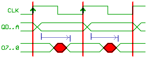
But there is one more problem:
Note the red marked areas.
The counter changes the values at it's outputs QA..QC shortly after every
rising edge on CLK.
But it takes the EPROM some time to stabilize the values at it's outputs
at O0..7.
With 74LS163 and a 70ns EPROM, it may take up to 100 ns after the rising
edge on CLK, until O0..7 are valid.
We only controlled LEDs, and the 74163 only reacts to the signal at !LD
at the rising edge of CLK, when O7 was stable.
We didn't mind, because timing/speed/propagation_delay was not important
until now.
But edge triggered TTL logic could become very confused from such a signal.
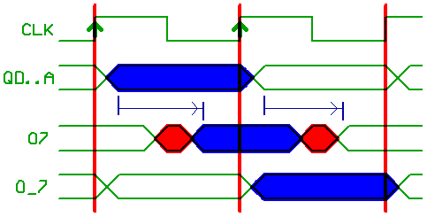
A good trick is, to take a 74374 latch, and to sample O0..O7 with the rising
edge on CLK, when they are stable.
The 74374 outputs O_0..O_7 will be clean/stable...
but are valid one CLK cycle later.
Neverthless, we now can use Q_7 to clock another 74374,
that latches the two Bits from our switches when the counter flips to zero,
and updates A4,A5 for "program start".
Instead of that, we could have used the 74377 synchronous latch, that features
a clock_enable (what could be directly connected to O7).
Another solution is to use/abuse a 74163 to work as a synchronous latch
(by disabling counting, and connecting !LD to the !CLR input of our counter
that feeds A0..3).
Theoretically, with 74LS163 and a 70 ns EPROM, we could reach CLK frequencies up to 8 MHz.
From what we learned so far, we could build some weird things.
With a few variations in hardware (counters, EPROM, and CLK frequency),
and some software to populate our EPROM with lookup tables, we could build a...
And a few other odd things, instead of "only" using a microcontroller.
Now for a short description, how to use what we learned in a homebuilt
processor.
[HOME] [UP]/ [BACK] [1] [2] [3] [4] [5] [6] [7] [8] [NEXT]
(c) Dieter Mueller 2005