Let's suppose, we have reset, two interrupts with different priority,
and normal operation. (like the 6502 has).
So we reserve two address lines of the EPROM (A14 and A15),
to select between:
In a processor, there also will be conditional jumps/branches.
We have to respond to the status of four flags: N,V,Z,C.
To save EPROM address lines, we use a 4:1 multiplexer to select
one of these flags, to be send into EPROM A13.
To select the flags, we need two Bits to control the multiplexer.
Fortunately, 6502 opcodes use Bit 6 and Bit 7 for that purpose.
6502 opcodes have a length of 8 Bit.
We can fetch them with a 74374 (as in the traffic light example),
and feed them into EPROM A5..A12.
EPROM A0..A4 can be connected to a 5 Bit counter (2*74163).
Now to summarize the EPROM address lines:
A 0.. 4 counter
A 5..12 opcode
A13     flag
A14..15 int/res
A13 is our flag status, and works like the normal_traffic/rush_hour
switch in our traffic light example.
A14 and A15 are the equivalent to our yellow blinkenlight switch:
when they bouth are 0, the processor works normal.
In our traffic light example, we used A4 and A5 to divide 64 Bytes
of EPROM memory into 4 areas,
each of them filled with one "program" that had 16 entries.
When building a processor with one 27512 microcode EPROM,
we divide 64kBytes into 8 blocks, 8 kB each.
Every block has 256 "programs"
(because there are 256 opcodes),
with up to 32 entries in every "program".
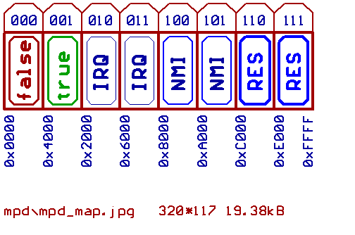
Blocks with an even number (0,2,4,6) are selected,
when the flag condition is 0 (false).
Blocks with an odd number (1,3,5,7) are selected,
when the flag condition is 1 (true).
When there is no interrupt or reset, block 0 and block 1 are
used to handle the 256 opcodes.
For all opcodes, that are no conditional jumps/branches,
the according "program" is identical in block 0 and block 1.
For our low priority interrupt, block 2 and block 3 both
contain 256 "programs".
All those 512 "programs" are identical (since the interrupt
overrides flags and opcodes).
The processor saves PC and status_register on stack,
and loads the PC with the IRQ vector.
We also have to disable the level_sensitive IRQ input.
Block 4 and block 5 handle the (edge triggered) NMI.
Block 6 and block 7 are responsible for the reset.
We have 32 entries for every "program", what means that the
reset signal should be active for more than 32 microcode cycles,
to ensure a correct reset operation.
Warning: If one "program" exceeds more than 32 entries,
it will corrupt the following/next "program",
and the assembler won't tell you about it.
There would be a trick to get along with only two blocks
(256 "programs" each),
but it will require some additional hardware.
Since we use a latch to fetch the opcode (74374 for instance),
we could wire the outputs of another latch in parallel, that would
"take over" during reset and interrupt to generate three (fake)
opcodes, that handle RES, NMI, IRQ.
We would end up with 253 usable opcodes, instead of 256.
But with a single EPROM, we won't go far.
From my own experience, it is better to go with a 24 or 32 Bit
wide microcode, because it allows us to run those EPROMs as the
slowest part of our processor.
Imagine three or four 27512, with the address lines connected together.
Some care must be taken, because the assembler still operates with
single bytes, while the EPROMs use 32 Bit longwords.
In other words: assembler address = EPROM address * 4.
Funny thing is, that the old DOS version of AS that I used seems
always to generate a 32kB sized binary file,
regardless of the size of the input file.
Decided to use this as a feature.
32kB is equal to 8k Longwords, what would cover A0..A12 of the
microcode EPROMs.
That is: our 5 Bit microcode counter, and the 8 Bit command latch.
In other words: the assembler generates one of our 8 blocks !
(If you choose to go that way with another assembler, it could become
necessary to write a tool for expanding such files to 32kB.)
Decided to send the microcode source file 5 times through the assembler
with different "switches" set/cleared
(since there are 5 different contents, a block may have),
copy them together to one 8*32kB sized binary file, and split them into
4*64kB to fit into the four 27512 EPROMs.
It is possible, to tell the assembler, what part of the source code to
process, and what part to ignore.
The structure for our example would look like this:
 IFNDEF IRQ
  IFNDEF NMI
   IFNDEF RES

    ORG $00*$20*4 ;brk
    ;"program" of first opcode
    ORG $01*$20*4 ;lda (ind,x)
    ;.....
    ORG $ff*$20*4 ;
    ;"program" of last opcode

   ENDIF
  ENDIF
 ENDIF

 IFDEF IRQ
 ;256 identical "programs", that handle IRQ
 ENDIF

 IFDEF NMI
 ;256 identical "programs", that handle NMI
 ENDIF

 IFDEF RES
 ;256 identical "programs", that handle RES
 ENDIF
Now for the conditional jumps/branches, our main difference between block 0
and block 1.
Since the flags change at the rising edge of CLK, and jumps/branches usually
don't modify any flags,
it's possible to connect the output of the flag
multiplexer directly to microcode EPROM A13.
There would be two macros:
M_TBR for taking a branch, and M_NTBR for not taking a branch.
Bouth macros first increment PC to point to the next Byte in program memory
(what would be the branch offset).
After that moment, flags should be valid/stable, because from that point
M_NTBR only increments the PC
and fetches the next opcode (as known from
M_NEXT), while M_NTBR reads the offset from data_bus
(while incrementing PC again), adds it to PC and then reads the next
opcode.
Selecting the flags is done by hardware (since the flag multiplexer is
controlled by two bits from the opcode).
All we have to do is to put M_NTBR into block 0 and M_TBR into block 1
if we want to jump/branch on a "true" flag condition (BCS, for instance).
For a branch on a "false" flag condition (such as BCC), put M_TBR into
block 0 and M_NTB into block 1, and that's all there is to it.
  ORG $90*$20*4  ;bcc, branch if C=0
  IFDEF FLAG_LO  ;Flag encoded by hardware
   M_TBR         ;take branch
  ELSEIF
   M_NTBR        ;not take branch
  ENDIF

  ;.....

  ORG $b0*$20*4  ;bcs, branch if C=1
  IFDEF FLAG_LO  ;Flag encoded by hardware
   M_NTBR        ;not take branch
  ELSEIF
   M_TBR         ;take branch
  ENDIF
When passing this example through the assembler, FLAG_LO is active
[HOME] [UP]/ [BACK] [1] [2] [3] [4] [5] [6] [7] [8] [NEXT]
(c) Dieter Mueller 2005