 |
CMSIS-Zone (Preview)
Version 0.0.1
System Resource Management
|
 |
CMSIS-Zone (Preview)
Version 0.0.1
System Resource Management
|
The Zone Description Format uses standard XML annotations and is defined in the schema file ZONE.xsd. It is intended to provide a tool vendor agnostic storage format for
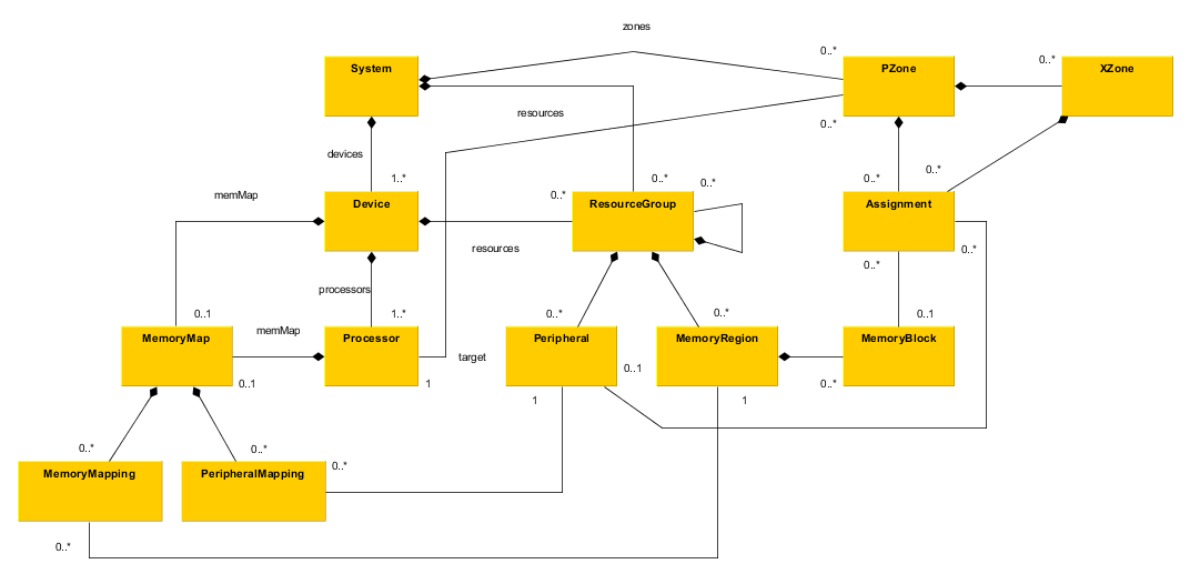
In the following diagram the overall structure of the Storage Data Model is depicted. The storage format is derived from the model.

The storage model is developed based on the domain and can be seen as the domain model as well. Its main purpose is to capture all information about presumable embedded systems and microcontroller devices.
Todays available system-on-modules (SoM) and system-on-chips (SoC) already physically outlines the overall composition. It seems to be viable to stick with todays system structures. It's not likely that this structure will change drastically.
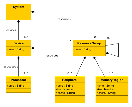
A detailed view on the decomposition of an arbitrary SoM is given in the diagram below.

The SoM itself (System) can be seen as a composition of one or more SoCs (Device) combined with an arbitrary amount of board-level resources, i.e. off-chip memory (Memory) and peripheral (Peripheral). In turn each SoC is a composition of one or more processor elements (Processor, PE) with chip-level resources, i.e. on-chip memory and peripheral.
Private memory and peripheral resources local to a dedicated PE has been simplified. These can also be seen as chip-level resources.
The grouping (ResourceGroup) is intended to allow structural grouping of resources elements, i.e. by type or bus structure.
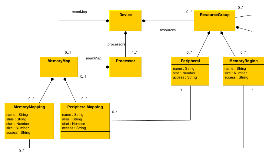
name attributes) are typically used as references and hence must be unique per class. Duplicate names are allowed if object hierarchies do not overlap. I.e. resources contained on two separate SoCs may have the same name but the name of a SoM level resource must not be reused on SoC level.Most of the Multi-Core-SoCs available today show uniform memory maps. But in principle the logical memory address used to address a certain resource may vary between multiple PEs on the same SoC. Taking this into account leads to memory map specification on both SoC and PE level, see diagram below.

The memory maps specified on SoC and PE level are additive, i.e. the PEs actual memory map is the combination of both. This split allow the specification of uniform memory maps without duplication. Only the non-uniform parts need to be specified on PE level.
Each resource can be mapped as often as needed, i.e. to reflect multiple memory aliases. By default the name attribute is used to identify the resource to be mapped. In order to map the same resource multiple times into a PEs memory space the alias attribute must be given to identify the resource instead. The mapping names must be unique per PE because they are used as references later.
The attributes of the mapping are merged with those of the resource mapped. This allows the mapping of an individual PE to enhance the basic attributes of a resource. For example a memory resource that is basically readable/writeable/executable might be mapped to a PE as readonly memory.
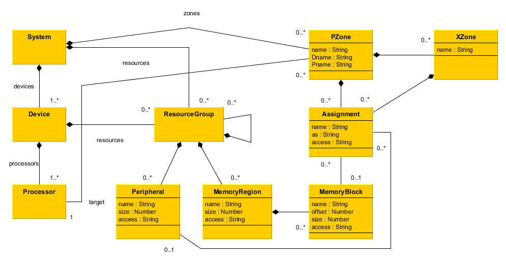
A system can be split into an arbitrary amount of project zones (PZone). And each PZone can be further split into execution zones (XZone). Resources used by an individual zone are represented using assignments (Assignment). Refer to the diagram below.

Each PZone is assigned to a dedicated PE which is selected to execute the resulting software part. The PE is referenced by the unique combination of Dname and Pname attributes. The XZones are contained in the PZone they belong to.
Both PZones and XZones can have arbitrary assignments to available resources visible to the assigned PE. Assignments to SoC level resources not part of the SoC the PE is located on are illegal. Such assignments cannot be represented because the unique reference is built from PZone::Dname and Assignment::name.
As a resource may be visible to the enclosing PE using multiple mappings the as attribute can be used to distinguish which alias is used for access. Selecting the correct alias is significant because of the effective access attributes resulting from merging Resource.access, MemoryMapping.access/PeripheralMapping.access and Assignment.access.
Whilst peripheral resources can be assigned directly memory resources need to be split into blocks (MemoryBlock). A block can be seen as an arbitrary part of the physical memory. Individual blocks can be defined using modified access attributes, e.g. for having dedicated executable or readonly regions in RAM.
The XML schema is defined hierarchically with the following top-level elements: