🌟T-Display-S3
English | 中文
[](https://github.com/Xinyuan-LilyGO/T-Display-S3/actions/workflows/platformio.yml)
[](https://github.com/Xinyuan-LilyGO/T-Display-S3/actions/workflows/arduino_ci.yml)
## 1. Supported Products
| Product (PinMap) | SOC | Flash | PSRAM | Resolution | Size |
| ----------------------- | ---------- | ----- | -------- | ---------- | -------- |
| [T-Display-S3][1] | ESP32-S3R8 | 16MB | 8MB(OPI) | 170x320 | 1.9 Inch |
| [T-Display-S3-Touch][2] | ESP32-S3R8 | 16MB | 8MB(OPI) | 170x320 | 1.9 Inch |
| [T-Display-S3-MIDI][3] | | | | | |
[1]: https://www.lilygo.cc/products/t-display-s3?variant=42589373268149
[2]: https://www.lilygo.cc/products/t-display-s3?variant=42351558590645
[3]: https://www.lilygo.cc/products/t-display-s3?variant=43164741632181
## 2. Examples
```bash
./examples/
├── Arduino_GFXDemo # Arduino_GFX example
├── Arduino_GFX_PDQgraphicstest # Arduino_GFX example
├── GetBatteryVoltage # Get battery voltage example
├── I2CScan # Scan for external devices using I2C
├── ImageScroll # Image scrolling example by @Rudi Ackermann
├── MPR121TouchSensor # Example of using MPR121 capacitive touch
├── PCBClock # TFT_eSPI PCBClock example by @VolosR
├── PokerS3 # TFT_eSPI PokerS3 example by @VolosR
├── SerialExample # Example of using serial communication
├── T-Display-S3-MIDI # T-Display-S3-MIDI Shield example
├── T-Display-S3-BLE-Receiver # Wireless BLE MIDI receiver with piano display (ESP32_Host_MIDI) by @sauloverissimo
├── T-Display-S3-BLE-Sender # BLE MIDI sender with auto-play sequences (ESP32_Host_MIDI) @sauloverissimo
├── T-Display-S3-Piano # USB MIDI Piano visualizer with chord detection (ESP32_Host_MIDI + Gingoduino) @sauloverissimo
├── T-Display-S3-Piano-Debug # MIDI event monitor with raw packet inspector (ESP32_Host_MIDI) @sauloverissimo
├── T-Display-S3-Gingoduino # Real-time chord detection and harmonic analysis (ESP32_Host_MIDI + Gingoduino) @sauloverissimo
├── T-Display-S3-Queue # MIDI event queue visualizer for debugging (ESP32_Host_MIDI) @sauloverissimo
├── T-Display-S3-USB-Device # BLE-to-USB MIDI bridge — T-Display-S3 as USB MIDI interface (ESP32_Host_MIDI) @sauloverissimo
├── T-Display-S3-Music-Explorer # Interactive music theory explorer with audio synthesis (Gingoduino) @sauloverissimo
├── TFT_Rainbow # TFT_eSPI example
├── factory # Factory example
├── lv_demos # LVGL demo
├── nes # NES game emulator
├── ota # Over-the-air upgrade example
├── sd # T-Display-TF Shield example
├── tft # TFT_eSPI example
├── touch_test # Capacitive touch test example
├── usb_hid_pad # Capacitive Touch Screen Simulation USB HID Example
├── ULP_ADC # ADC detection for ULP-FSM (arduino_esp32 version: 3.0.0-rc3)
└── ULP_Count # Register counting for ULP-FSM (arduino_esp32 version: 3.0.0-rc3)
```
## 3. PlatformIO Quick Start (Recommended)
1. Install [Visual Studio Code](https://code.visualstudio.com/) and [Python](https://www.python.org/).
2. Search for the `PlatformIO` plugin in the VS Code extension marketplace and install it.
3. After installation, restart VS Code.
4. In VS Code, select `File` > `Open Folder` > choose the `T-Display-S3` directory.
5. Wait for third-party dependent libraries to finish installing.
6. Open the `platformio.ini` file.
7. Uncomment one of the lines `default_envs = xxxx` — make sure only one line is active.
8. Click the (checkmark) icon in the lower left corner to compile.
9. Connect the board to your computer via USB.
10. Click (arrow) to upload firmware.
11. Click (plug icon) to monitor serial output.
12. If upload fails or the USB device keeps flashing, check the **FAQ** below.
> [!TIP]
> If you encounter unexpected build errors, try re-cloning (or re-downloading) this repository first. Before compiling, click the **Clean** button in the PlatformIO toolbar to remove stale build artifacts, then try building again.
## 4. Arduino IDE Manual Installation
1. Install [Arduino IDE](https://www.arduino.cc/en/software).
2. In Arduino Preferences, on the Settings tab, enter the following URL in the `Additional boards manager URLs` input box:
```
https://raw.githubusercontent.com/espressif/arduino-esp32/gh-pages/package_esp32_index.json
```
> **Note:** The test phase uses version 2.0.14. Versions above 2.0.14 may not work correctly — please downgrade if you encounter issues. As of 2024/08/02, TFT_eSPI does not work on versions higher than 2.0.14 (see [TFT_eSPI#3329](https://github.com/Bodmer/TFT_eSPI/issues/3329)).
3. Download `T-Display-S3` and move it to your Arduino library folder (e.g. `C:\Users\YourName\Documents\Arduino\libraries`).
4. Copy all folders in the [lib folder](./lib/) to your Arduino library folder.
5. Navigate to the `T-Display-S3/examples` directory.
6. Select any example and double-click the `.ino` file to open it.
7. In Arduino IDE, go to `Tools` and configure the following:
| Arduino IDE Setting | Value |
| ------------------------------------ | ---------------------------------- |
| Board | **ESP32S3 Dev Module** |
| Port | Your port |
| USB CDC On Boot | Enable |
| CPU Frequency | 240MHz (WiFi) |
| Core Debug Level | None |
| USB DFU On Boot | Disable |
| Erase All Flash Before Sketch Upload | Disable |
| Events Run On | Core1 |
| Flash Mode | QIO 80MHz |
| Flash Size | **16MB (128Mb)** |
| Arduino Runs On | Core1 |
| USB Firmware MSC On Boot | Disable |
| Partition Scheme | **16M Flash (3M APP/9.9MB FATFS)** |
| PSRAM | **OPI PSRAM** |
| Upload Mode | **UART0/Hardware CDC** |
| Upload Speed | 921600 |
| USB Mode | **CDC and JTAG** |
> Options in **bold** are required. Others should be selected based on your actual conditions.
8. Click `Upload` and wait for compilation and writing to complete.
9. If upload fails or the USB device keeps flashing, check the **FAQ** below.
- You can also choose `LilyGo T-Display-S3` as the board, but the partition table is fixed to **16M Flash (3M APP/9.9MB FATFS)**.
- [T-Display-S3 Arduino IDE Record](https://www.youtube.com/watch?v=PgtxisFvMcc)
## 5. ESP-IDF
For the ESP-IDF version of T-Display-S3 examples, see [LilyGo-Display-IDF](https://github.com/Xinyuan-LilyGO/LilyGo-Display-IDF).
## 6. MicroPython
- [russhughes/st7789s3_mpy](https://github.com/russhughes/st7789s3_mpy)
- [lilygo-micropython](https://github.com/Xinyuan-LilyGO/lilygo-micropython)
## Pinout
| Name | GPIO | Note |
| ------------ | ---- | ----------------- |
| LCD BL | 38 | Backlight |
| LCD D0 | 39 | |
| LCD D1 | 40 | |
| LCD D2 | 41 | |
| LCD D3 | 42 | |
| LCD D4 | 45 | |
| LCD D5 | 46 | |
| LCD D6 | 47 | |
| LCD D7 | 48 | |
| LCD RST | 5 | Reset |
| LCD CS | 6 | Chip Select |
| LCD DC | 7 | Data/Command |
| LCD WR | 8 | Write |
| LCD RD | 9 | Read |
| Power On | 15 | LCD power control |
| Button 1 | 0 | BOOT button |
| Button 2 | 14 | |
| Battery Volt | 4 | ADC |
| IIC SCL | 17 | |
| IIC SDA | 18 | |
| Touch INT | 16 | Touch interrupt |
| Touch RES | 21 | Touch reset |
| SD CMD | 13 | SD card |
| SD CLK | 11 | SD card |
| SD D0 | 12 | SD card |
> [!IMPORTANT]
>
> **Note:** GPIO15 is the peripheral power control pin. You must set it HIGH before using the board, otherwise the LCD and other peripherals will not work. For battery-powered or 5V Pin Header usage:
> ```c
> pinMode(15, OUTPUT);
> digitalWrite(15, HIGH);
> ```
> SD card pins (SD CMD/CLK/D0) are only available on boards with the SD Shield add-on. The standard T-Display-S3 board does not have an onboard SD card slot.
>
> The battery ADC pin can only read the battery voltage when the USB-C port is not plugged in; it cannot read the battery voltage after the USB-C port is plugged in.
>
## 7. ESP32 Basic Examples
- [BLE Examples](https://github.com/espressif/arduino-esp32/tree/master/libraries/BLE)
- [WiFi Examples](https://github.com/espressif/arduino-esp32/tree/master/libraries/WiFi)
- [SPIFFS Examples](https://github.com/espressif/arduino-esp32/tree/master/libraries/SPIFFS)
- [FFat Examples](https://github.com/espressif/arduino-esp32/tree/master/libraries/FFat)
- For more ESP32 chip function examples, see [arduino-esp32-libraries](https://github.com/espressif/arduino-esp32/tree/master/libraries)
## 8. Resources
| Product (PinMap) | Schematic | Dimensions | PCB 3D | PinMap |
| ----------------------- | ------------------------------------------------------- | --------------------------- | ----------------------------------------- | ---------------------------------------- |
| [T-Display-S3][1] | [schematic](./schematic/T_Display_S3.pdf) | [DWG](./dimensions/PCB.dwg) | [STP](./dimensions/t-display-s3-full.stp) | [PinMap](./image/T-DISPLAY-S3.jpg) |
| [T-Display-S3-Touch][2] | [schematic](./schematic/T_Display_S3.pdf) | [DWG](./dimensions/PCB.dwg) | [STP](./dimensions/t-display-s3-full.stp) | [PinMap](./image/T-DISPLAY-S3-TOUCH.png) |
| [T-Display-S3-MIDI][3] | [schematic](./schematic/SCH_T-Display-S3-MIDI_V1.1.pdf) | N.A | N.A | N.A |
## 9. FAQ
1. **The screen does not light up when using battery.**
- When T-Display-S3 is powered by battery or 5V Pin Header, GPIO15 must be set to HIGH to turn on the backlight.
- Add the following at the beginning of `setup()`:
```cpp
void setup() {
// Turn on display power
pinMode(15, OUTPUT);
digitalWrite(15, HIGH);
}
```
2. **The program uploads successfully, but nothing is displayed on the screen.**
- If you are using **TFT_eSPI**, try running `Arduino_GFXDemo` first. If nothing is displayed, the issue is likely with the hardware.
- If `Arduino_GFXDemo` works but **TFT_eSPI** does not, the `User_Setup_Select` configuration may have been overwritten. See FAQ #3 to reconfigure **TFT_eSPI**.
3. **How to update TFT_eSPI or verify the pin configuration is correct?**
- Search for **TFT_eSPI** in the Arduino IDE Library Manager and click Update.
- Navigate to the TFT_eSPI installation folder (e.g. `C:\Users\YourName\Documents\Arduino\libraries\TFT_eSPI`).
- Open `User_Setup_Select.h`, comment out (or delete) the default `#include ` line.
- Find `Setup206_LilyGo_T_Display_S3.h`, uncomment it, save, and close:
```cpp
#include // LilyGo T-Display S3 (ESP32S3 + ST7789 170x320 TFT)
```
4. **Cannot upload any sketch — please enter upload mode manually.**
- Connect the board via USB cable.
- Press and hold the **BOOT** button.
- While holding **BOOT**, press the **RST** button.
- Release **RST**.
- Release **BOOT**
- Upload the sketch.
- Press **RST** to exit download mode.
5. **If you use an external power supply instead of USB-C, please disable the CDC option.** The board waits for USB access on startup when CDC is enabled.
- Arduino IDE: `Tools` > `USB CDC On Boot` > `Disable`
> Disabling USB CDC turns off Serial redirection to USB-C. Serial output will come from GPIO43 and GPIO44 instead.
- PlatformIO: add the following to `platformio.ini`:
```ini
build_flags =
; -DARDUINO_USB_CDC_ON_BOOT=1 ; Enable: prints and waits for terminal on startup
-UARDUINO_USB_CDC_ON_BOOT ; Disable: no blocking on startup
```
6. **If none of the above works, flash the factory firmware for quick verification.** See [here](https://github.com/Xinyuan-LilyGO/T-Display-S3/tree/main/firmware).
7. **Can I use an external 5V pin for power?** See [issues/205](https://github.com/Xinyuan-LilyGO/T-Display-S3/issues/205).
8. **How to adjust the charging current?** The default charging current is 500mA. See [issues/230](https://github.com/Xinyuan-LilyGO/T-Display-S3/issues/230).
## LED Description
| Function | Color |
| ------------- | ----- |
| Charge LED | Red |
| V3V Indicator | Green |
### Charging Indicator LED Status
1. Flashes or dimly lights when no battery is connected.
2. Remains on while charging.
3. Turns off when fully charged.
### V3V Indicator
1. In USB mode, the green indicator stays on.
2. In battery power mode, GPIO15 lights up when high and turns off when low.
### WiFi antenna
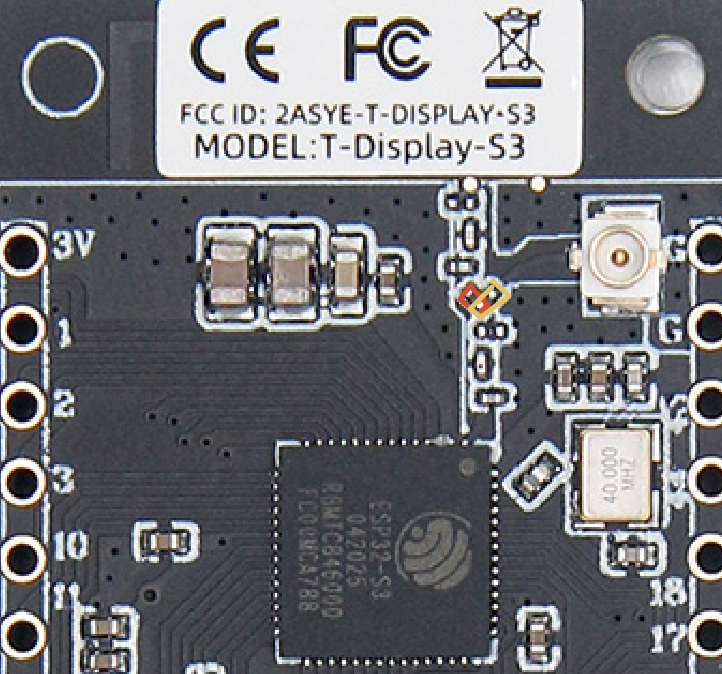
* The default is onboard antenna. If you need to use an external antenna, you need to rotate the resistor in the red position in the image below to the position highlighted in yellow to switch to external antenna mode.
 ### Electrical parameters
| Features | Details |
| ------------------------ | ----------- |
| 🔗USB-C input voltage | 5V |
| 🔋Battery voltage | 3.7V~4.2V |
| 🔋Battery Connector Model | JST 1.25 mm |
| 📍**VBUS** (pin header) | 5V |
| 📍**VBAT** (pin header) | 4.2V |
* 3V pin header load does not exceed 100mA
* The 5V pin header power source comes from USB-C, and the load capacity depends on the USB-C adapter