Examples > Analog I/O
Fading
Demonstrates the use of analog output (Pulse Width Modulation (PWM)) to fade an LED. PWM is a technique for getting an analog-like behavior from a digital output by switching it off and on very fast.
Hardware Required
- MSP-EXP430G2 LaunchPad
- 10k ohm resistor
- breadboard
- hook-up wire
- LED (available on-board)
Relevant Groundwork
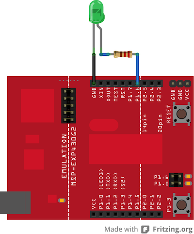
An LED connected to digital output pin 14 through a 220-ohm resistor. Note that pin 14 is connected to the green LED on the MSP-EXP430G2 LaunchPad. Also, it is important to note that not all pins on the LaunchPad are capable of generating a PWM signal using the analogWrite() function. To see all of the pins that support analogWrite(), visit the Energia pin-mapping guide.
Circuit
Schematic
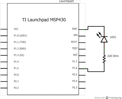
image developed using Fritzing. For more circuit examples, see the Fritzing project page
Code Explanation
None. See comments below.
Code
/*
  Fading

  This example shows how to fade an LED using the analogWrite() function.

  The circuit:
  * LED attached from digital pin 14 to ground.

  Created 1 Nov 2008
  By David A. Mellis
  modified 16 Apr 2013
  By Adrian Fernandez


  This example code is in the public domain.

*/


int ledPin = 14;    // LED connected to digital pin 9

void setup()  {
  // nothing happens in setup
}

void loop()  {
  // fade in from min to max in increments of 5 points:
  for(int fadeValue = 0 ; fadeValue <= 255; fadeValue +=5) {
    // sets the value (range from 0 to 255):
    analogWrite(ledPin, fadeValue);
    // wait for 30 milliseconds to see the dimming effect
    delay(30);
  }

  // fade out from max to min in increments of 5 points:
  for(int fadeValue = 255 ; fadeValue >= 0; fadeValue -=5) {
    // sets the value (range from 0 to 255):
    analogWrite(ledPin, fadeValue);
    // wait for 30 milliseconds to see the dimming effect
    delay(30);
  }
}
Working Video
(Insert Video Here)Try it out:
See Also:
- for()
- analogWrite()
- delay()
- AnalogReadSerial - read a potentiometer, print its state to the serial monitor
- AnalogInOutSerial - read an analog input, map its values, and then use that information to dim or brighten an LED.
- Fade - use an analog input to fade an LED
- Calibration - calibrating analog sensor readings
Corrections, suggestions, and new documentation should be posted to the Forum.
The text of the Energia reference is licensed under a Creative Commons Attribution-ShareAlike 3.0 License. Energia reference is based on the Arduino reference. Code samples in the reference are released into the public domain.