Team X67 # WRO 2026 Future Engineers β€” Team X67 ## πŸš— *Enner Valencia* **An autonomous car built from a custom PCB, a 3D-printed rack-and-pinion chassis, laser distance sensors, a gyroscope and our own on-board computer vision** *Colegio Americano de Guayaquil Β· Ecuador*

Enner Valencia
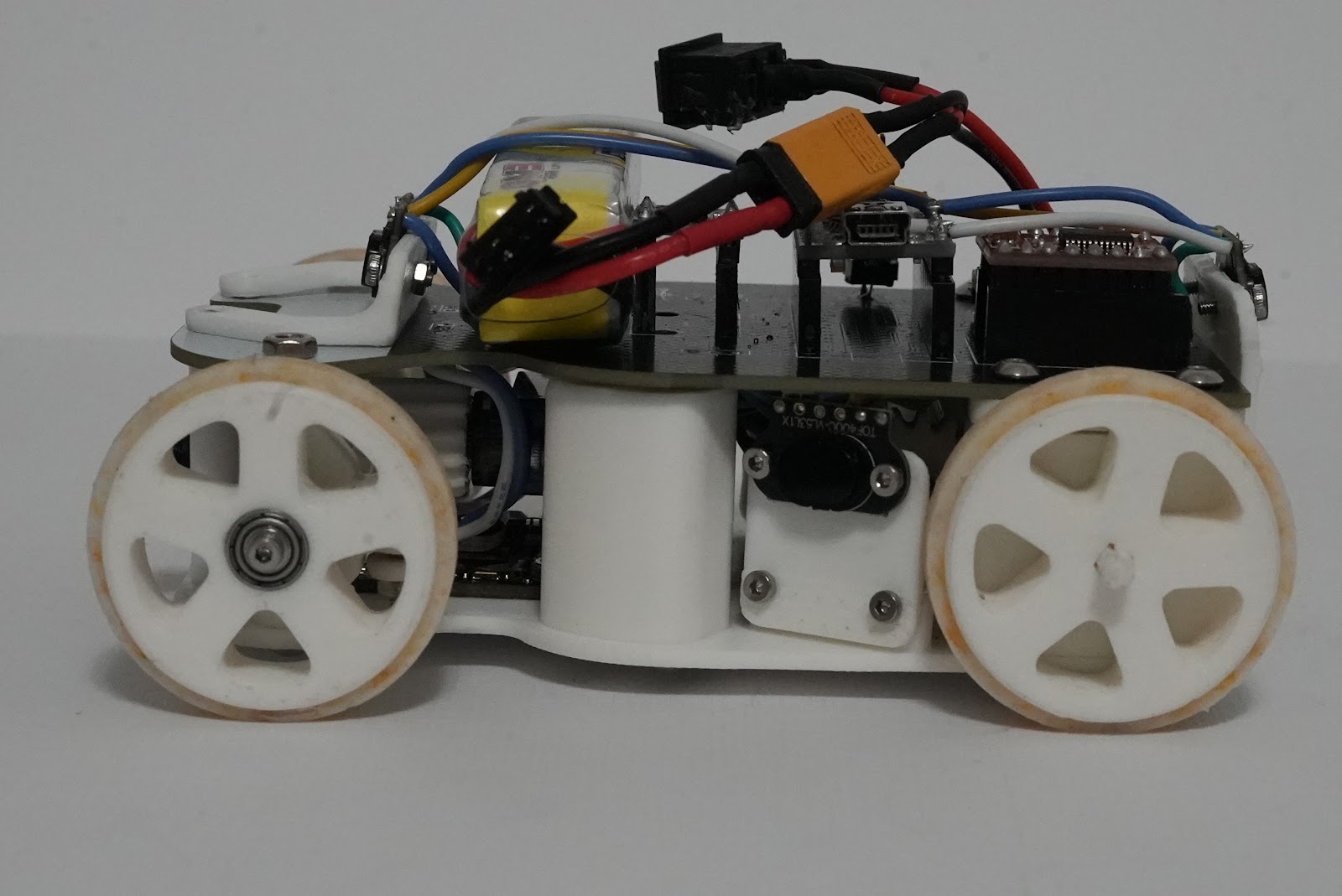
--- This repository documents the car that Team X67 built for the **World Robot Olympiad 2026, Future Engineers** category. The car must drive three laps of a track whose inner walls move every round (**Open Challenge**). In the **Obstacle Challenge** it must also pass red pillars on their right and green pillars on their left, and finish by parallel parking. Here you will find the full engineering process (what we tried, what failed, the data, and why we changed it), the electrical design with its PCB and power budget, all the source code, and instructions to build, compile and upload everything. All documentation and code are in English. | | | |---|---| | **Size / mass** | 13 Γ— 9.5 Γ— 6 cm Β· 270 g (limits: 30 Γ— 20 Γ— 30 cm, 1.5 kg) | | **Main controller** | Arduino Nano (ATmega328P) | | **Vision** | ESP32-S3-CAM (OV2640) running our own colour-detection pipeline (320 Γ— 240, ~12.5 fps with pillars and floor lines) | | **Sensors** | 4 Γ— TOF400C laser distance sensors (VL53L1X), BMI160 gyroscope, motor encoder | | **Drive / steering** | One N20 12 V 1000 rpm motor with encoder β†’ 1 : 1 rear differential Β· parallel **rack-and-pinion** steering (module 1 mm) with an MG90 servo | | **Chassis** | 3D-printed PLA base (v3, all joints screwed) carrying a custom PCB (EasyEDA β†’ JLCPCB) Β· cast silicone tyres | | **Power** | 3S HV LiPo 11.4 V 380 mAh Β· CN3903 5 V / 3 A buck converter | --- ## Contents 1. [Repository structure](#1-repository-structure) 2. [The team](#2-the-team) 3. [The challenge](#3-the-challenge) 4. [Vehicle photos and videos](#4-vehicle-photos-and-videos) 5. [Mobility and mechanical design](#5-mobility-and-mechanical-design) 6. [Power and sensor architecture](#6-power-and-sensor-architecture) 7. [Software architecture](#7-software-architecture) 8. [Open Challenge strategy](#8-open-challenge-strategy) 9. [Obstacle Challenge strategy](#9-obstacle-challenge-strategy) 10. [Systems thinking: constraints, trade-offs and risks](#10-systems-thinking-constraints-trade-offs-and-risks) 11. [Testing workflow and metrics](#11-testing-workflow-and-metrics) 12. [How to build, compile and upload](#12-how-to-build-compile-and-upload) 13. [Current status and next steps](#13-current-status-and-next-steps) 14. [Versions and release notes](#14-versions-and-release-notes) --- ## 1. Repository structure ``` . β”œβ”€β”€ README.md ← this file: complete overview of the car β”œβ”€β”€ CHANGELOG.md ← versions and release notes β”œβ”€β”€ docs/ β”‚ β”œβ”€β”€ ENGINEERING_JOURNAL.md ← day-by-day engineering process: 58 problems, data and decisions β”‚ └── images/ ← plots used in the journal β”œβ”€β”€ schemes/ ← schematic, wiring diagram, PCB, power budget, BOM, datasheets β”œβ”€β”€ src/ ← all source code (see src/README.md) β”‚ β”œβ”€β”€ hardware-tests/ ← one sketch per component β”‚ β”œβ”€β”€ obstacle-challenge/ ← camera vision, straight with pillars, line test, Pillar Vision Lab β”‚ └── tools/scenario-roulette/← generates official WRO 2026 track scenarios to test on β”œβ”€β”€ models/ ← 25 STL files of every printed part, renders, CAD v1–v3, tyre moulding β”œβ”€β”€ t-photos/ ← team photos (official and fun) β”œβ”€β”€ v-photos/ ← the six official views of the vehicle + all parts laid out β”œβ”€β”€ video/ ← links to the driving videos └── other/ ← component pictures, PCB manufacturing, tyre casting, build process, retired parts ``` | Folder | Detailed documentation | |---|---| | ⚑ Electrical system, PCB, power budget, BOM | [schemes/README.md](schemes/README.md) | | πŸ’Ύ Source code, every sketch explained | [src/README.md](src/README.md) | | πŸ““ Engineering process | [docs/ENGINEERING_JOURNAL.md](docs/ENGINEERING_JOURNAL.md) | | πŸš— Vehicle photos | [v-photos/README.md](v-photos/README.md) | | πŸ‘₯ Team photos | [t-photos/README.md](t-photos/README.md) | | πŸŽ₯ Videos | [video/video.md](video/video.md) | | βš™οΈ 3D models (25 STL), CAD iterations, tyre casting | [models/README.md](models/README.md) | | 🧰 Build process, retired parts | [other/README.md](other/README.md) | --- ## 2. The team

Team X67
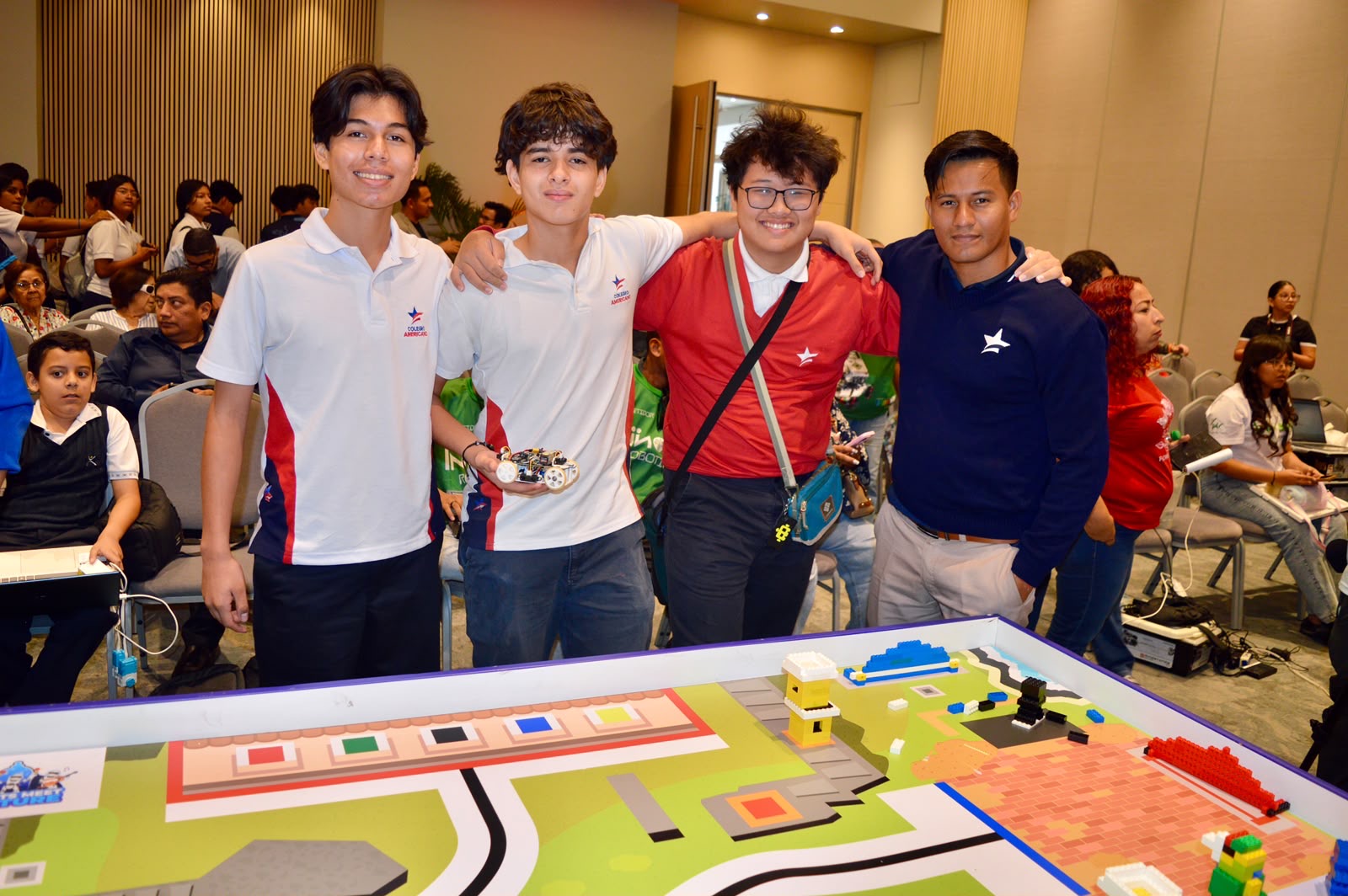
Team X67 and our coach at the WRO 2026 Ecuador national final.
This is our **first year** in the Future Engineers category. We are students of the Colegio Americano de Guayaquil robotics club. | Member | Role | |---|---| | **Eduardo Rivadeneira** | Electronics and PCB design, mechanical design, strategy integration. Robotics club since 2022 | | **Henry Riera Loza** | Software, sensors and computer vision, engineering journal and this repository. Robotics club since 2023 | | **Geovanny Li** | Computer vision research, software, strategy. Robotics club since 2023 | | **Henry Cercado** (coach) | Computer Science teacher and Computer Science engineer | ### Our names - **Team X67.** "67" started as a joke, so we decided to give it a meaning: *if you fall 6 times, you get up 7*. The **X** is a variable: anyone can live by it. - **The car is called *Enner Valencia***, after the striker of Ecuador's national football team. Like him, through every drop in performance (three broken servos, a burnt board, two chassis redesigns) it always comes back, no matter how many times it falls.

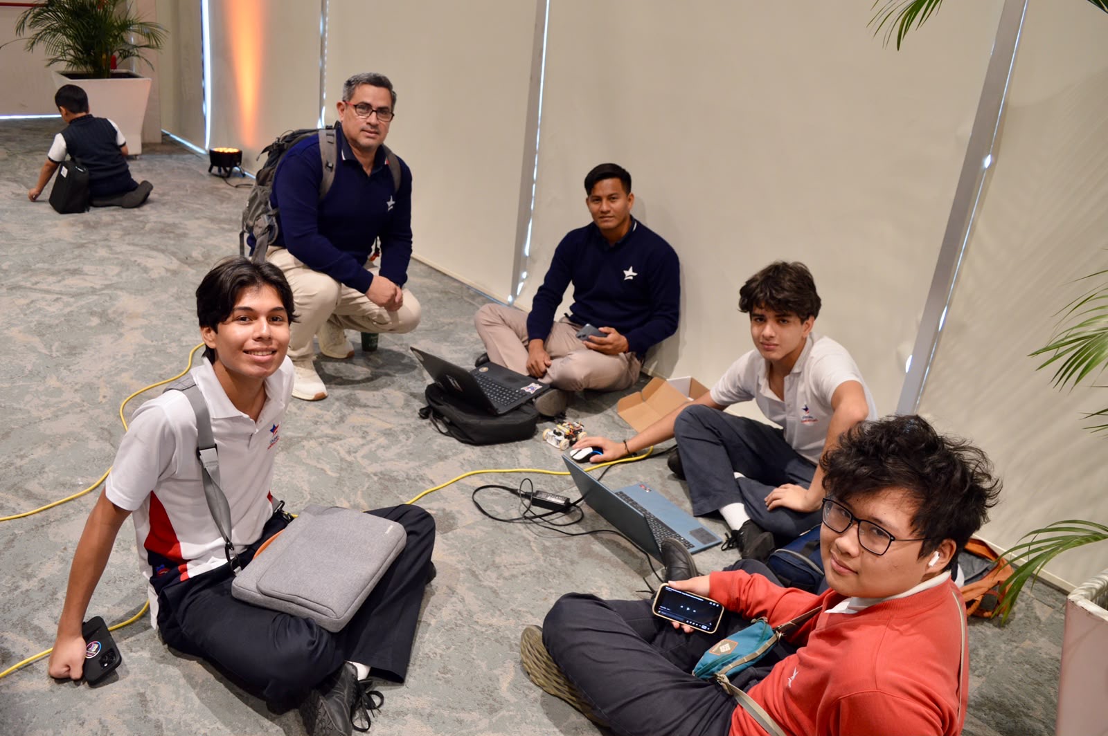
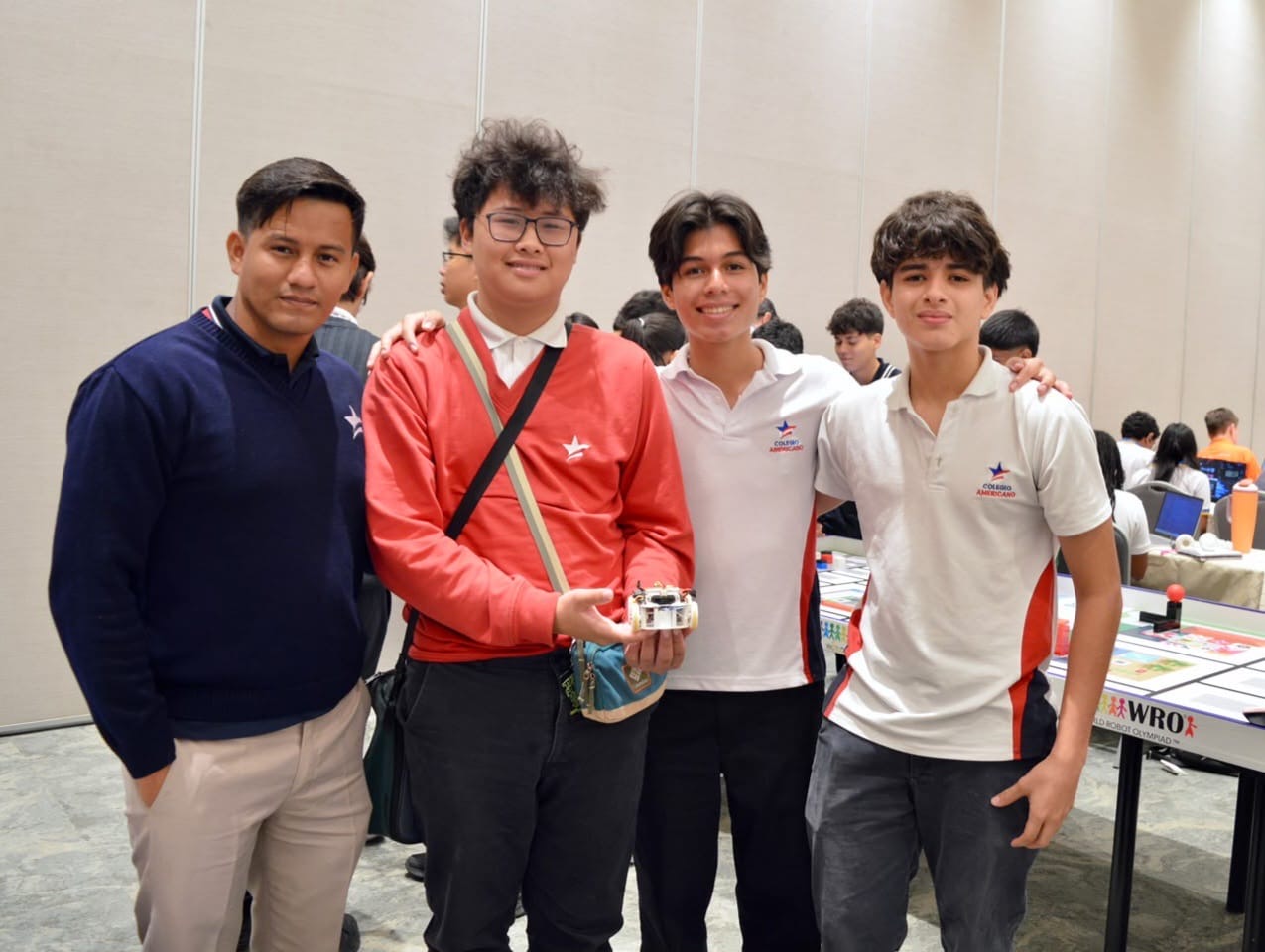
Debugging between rounds, and the team with the car at the national final.
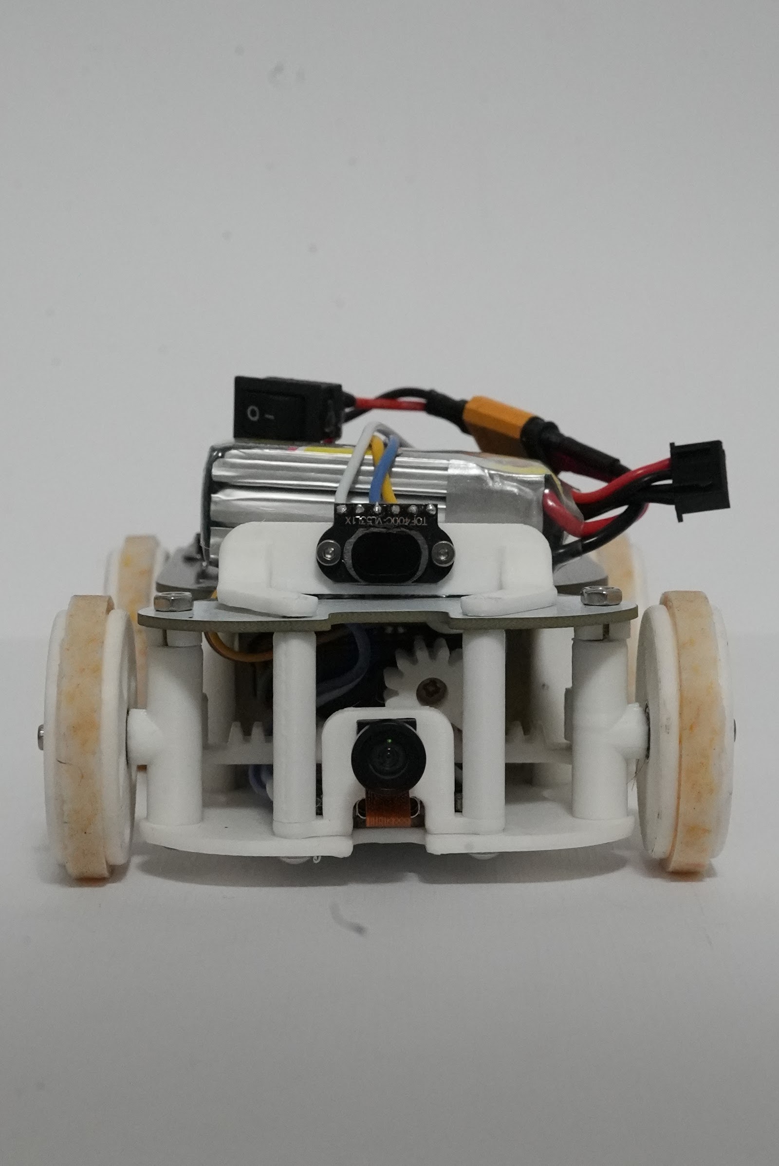
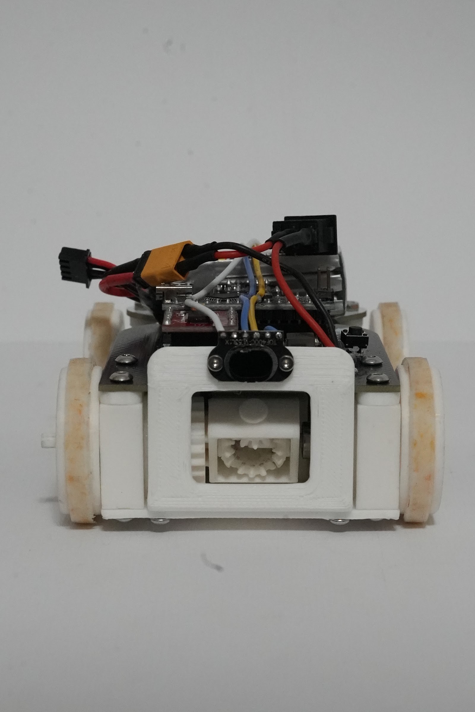
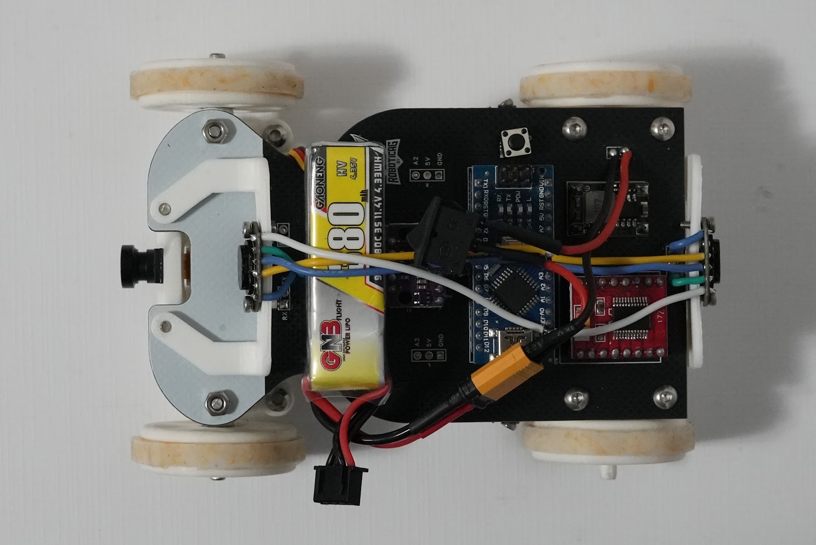
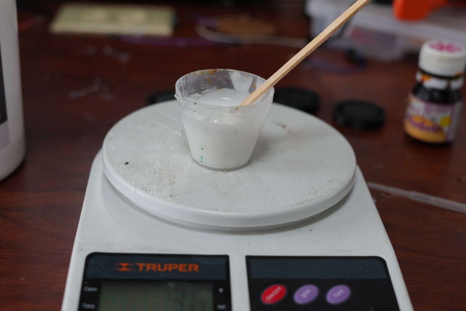
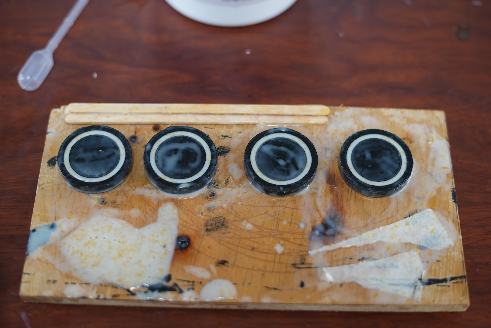
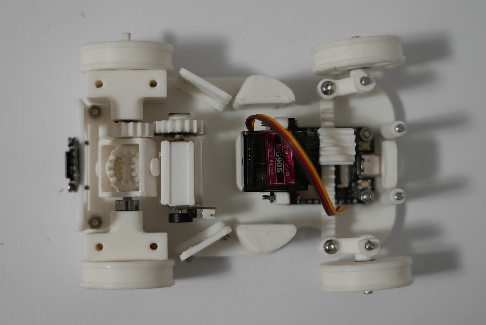
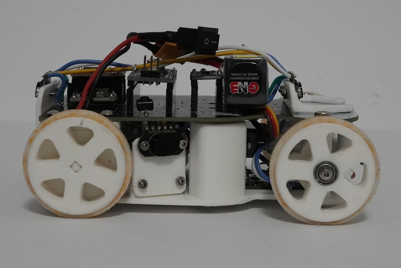
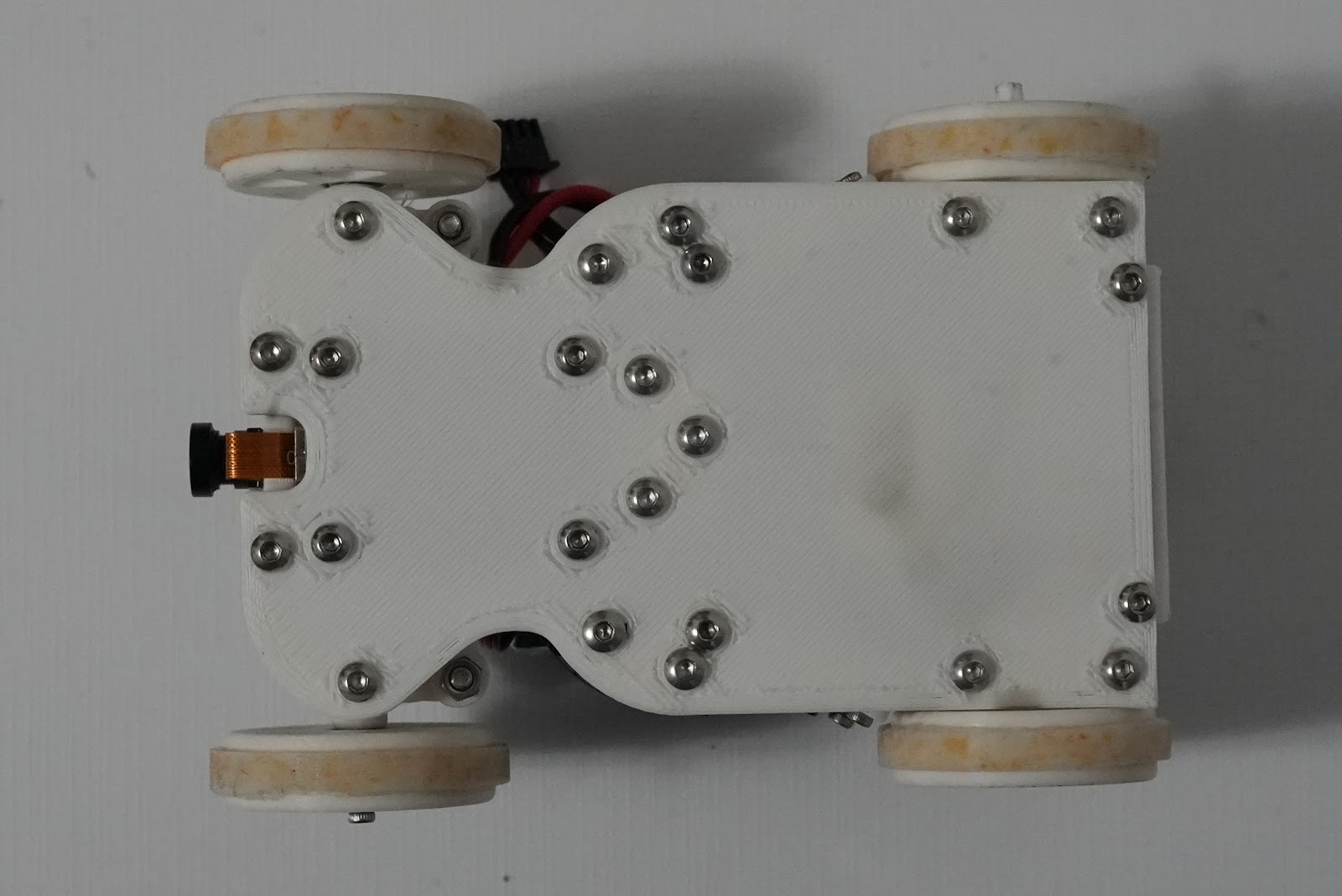
--- ## 3. The challenge | Challenge | Task | |---|---| | **Open Challenge** | Drive **3 laps** (3 minutes maximum) on a 3 Γ— 3 m field with 10 cm black walls. The inner walls are placed randomly every round, so each corridor is either 1000 mm or 600 mm wide (Β± 100 mm at the International Final); the starting section, starting zone and driving direction (clockwise or counter-clockwise) are also random. After 3 laps the car must stop by itself inside the starting section. The car **may not touch the outer wall** | | **Obstacle Challenge** | Drive **3 laps** (3 minutes maximum, corridors always 1000 mm) while obeying traffic signs: πŸŸ₯ **red** pillar β†’ pass on its **right**; 🟩 **green** pillar β†’ pass on its **left**. Then find the magenta parking lot (always in the starting section, length 1.5 Γ— car length) and **parallel park** without touching its limits | | **Documentation** | Public GitHub repository and engineering journal, scored with five criteria (mobility, power and sensors, software, systems thinking, reproducibility) | Constraints that shaped our design (from the [official rules](https://wro-association.org/)): maximum size 30 Γ— 20 Γ— 30 cm, maximum mass 1.5 kg, one drive axle with mechanically connected wheels, a steering system, one start button and one power switch, no wireless communication during the run. ### 3.1 Rules compliance How the car and this repository meet each rule of the *WRO 2026 Future Engineers General Rules* (version 15 January 2026) that affects our design: | Rule | Requirement | How we comply | |---|---|---| | 9.17 / 11.1 | Max 300 Γ— 200 Γ— 300 mm | 130 Γ— 95 Γ— 60 mm | | 11.2 | Max 1.5 kg | 270 g | | 11.3 / 11.4 | 4 wheels, one driving axle, one steering actuator; no omni or ball wheels; no differential-drive robot | 4 wheels, rear-wheel drive, one MG90 servo on a rack and pinion | | 11.5 / 11.13 | Max 2 driving motors, connected to the axle (no motor per side) | One N20 motor β†’ 1 : 1 mechanical differential on the rear axle | | 11.6 / 11.10 / 11.17 | Autonomous; no radio, Bluetooth or Wi-Fi during rounds; only wired links between components | The Nano has no radio. The camera board's Wi-Fi is **never started** in the competition code (the camera talks to the Nano by UART cable). `camera_webserver_emakefun` uses Wi-Fi and is a **bench test only** | | 9.6 / 9.10 / 9.11 / 9.14 | Placed switched off; one power switch; waiting state; one start button; pressing it starts the run | Power switch β†’ program calibrates the gyro and waits in `WAITING`; one push button on D10 starts the run | | 9.9 / 11.7 | No data entered by switches, part positions or sensor calibration before the round; no signals during the run | The program reads nothing from the team: the gyro offset is measured **automatically** by the program at power-on with the car still, and the turn direction and wall positions are detected by the sensors during the run | | 9.16 / 9.21 / App. A.4 | Drive in the round direction; reverse only within the section where it changed direction and the next one | Direction detected at the first corner. The only reverse manoeuvre is the undo of a wrong first turn, a short move inside the corner section (allowed, App. A.4 case 1) | | 9.18 | Do not move walls; in the Open Challenge do not touch the outer wall | The car follows the **inner** wall at a short distance, so it stays away from the outer wall; front safety brake | | 9.22 / 9.24.2 / 9.24.3 / App. A.2–A.3 | After 3 laps stop completely inside the starting section (no movement after 15 s; judged after 30 s still); passing into the next corner ends the round without the stop points | After the **12th** turn: short tuned straight, then **active brake held forever** (both TB6612FNG inputs HIGH) | | 9.23 | One repair per round; no program upload, no data entry | Nothing to configure: after a repair the car is switched on and started with the same button | | 8 (Obstacle) / 1.8.1 | Parking-lot start points only if a full lap is completed | Start position decided by the team before the round; parking still being designed | | 3.3 / 3.7 | Code and construction only by the team, own solution | All code written by the team; history visible in the commits and the journal | | 7 | Public GitHub repository in English; README β‰₯ 5000 characters (modules, link to electromechanical components, build / compile / upload); commented code; photos of every side, top and bottom; team photo; one YouTube video per challenge with β‰₯ 30 s of autonomous driving; β‰₯ 3 commits on time; repository public for 12 months after the event; hard copy at the International Final | See [Β§14.1 Submission checklist](#141-submission-checklist) | --- ## 4. Vehicle photos and videos | Front | Back | Top | |---|---|---| | | | | | **Left** | **Right** | **Bottom** | | | | | - All vehicle photos with descriptions: [v-photos](v-photos/README.md) - Driving videos: [video/video.md](video/video.md) β€” [autonomous driving on YouTube](https://www.youtube.com/watch?v=J5yrJuZZ5P8). The rules ask for **one video per challenge** (Open and Obstacle), each with at least 30 s of autonomous driving; the list in `video.md` shows which ones are ready. --- ## 5. Mobility and mechanical design All printed parts (25 STL files), the full STEP assembly, the CAD of every iteration and the tyre-casting process are in [models/README.md](models/README.md).
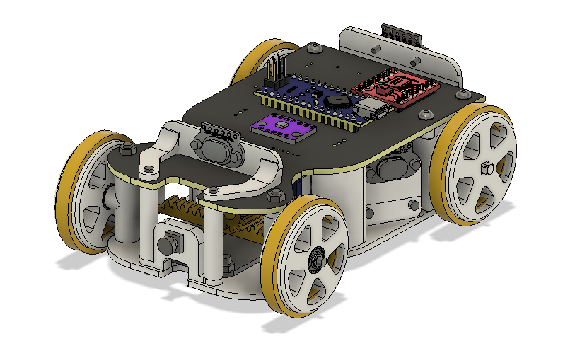
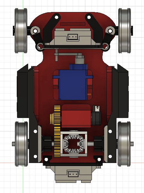
CAD assembly All parts
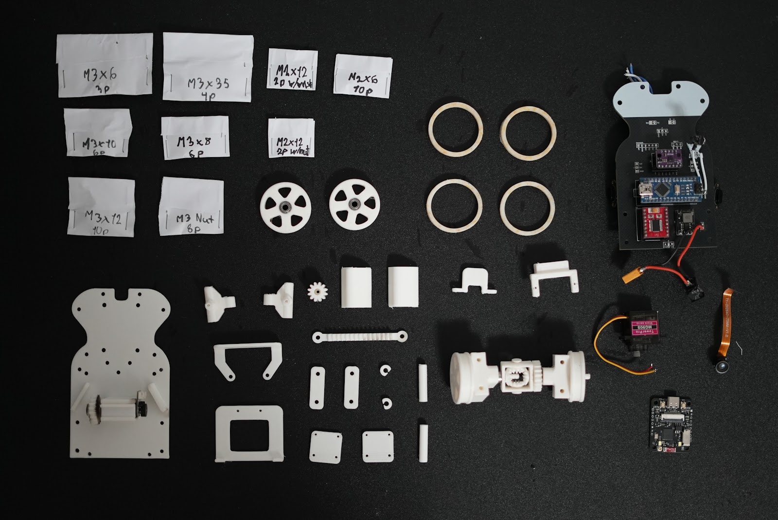
CAD assembly of chassis v3, and every part of the real car laid out before assembly.
### 5.1 Chassis - **Two layers:** a **3D-printed PLA base** (120 Γ— 70 mm) carries the drive train at the rear and the steering at the front; the **custom PCB** sits on printed supports above it and carries all the electronics. The 3S battery lies flat on the PCB. - **Size and mass:** 13 cm long, 9.5 cm wide, 6 cm high, **270 g**. That is less than half of the allowed length and width and under 20 % of the allowed mass. - **Why so small:** the narrowest corridor is 60 cm. A short, narrow car has more free space on each side to correct its path and to pass pillars, and a short wheelbase turns in a smaller radius. - **Stability:** the car is only 6 cm high and the heaviest parts (battery, motor, PCB) are in its lower half, so the centre of mass is low and the car does not roll in turns. The PCB is 1.6 mm FR-4 and is screwed to the base, which makes the whole chassis stiff. - **Everything is screwed:** in chassis v2 some parts were held with tape, which showed the design was incomplete. In v3 every joint is a screw, so the geometry does not change after a crash or after taking the car apart. ### 5.2 Drive - **One N20 12 V, 1000 rpm motor with a Hall encoder** drives both rear wheels through a **differential with a 1 : 1 gear ratio** (motor gear and differential gear both 22 mm). A single motor on one axle follows the rules (driving wheels must be mechanically connected), and the differential lets the inner and outer wheels turn at different speeds in corners, so the tyres do not scrub and the car follows the steering angle precisely. - **Speed reasoning:** with 41 mm wheels, each wheel revolution moves the car Ο€ Γ— 41 mm β‰ˆ 129 mm, so 1000 rpm at 1 : 1 gives a theoretical top speed of β‰ˆ 129 mm Γ— 1000 / 60 β‰ˆ **2.1 m/s**. That is far more than we need: our control loop is designed for β‰ˆ 0.3–0.4 m/s, where the side TOF sensors (one reading every 50 ms) see a new value every 1.5–2 cm and one 8-reading decision takes less than one car length (Β§10.4). We drive the motor with a PWM duty cycle well below 100 %, which also leaves torque available for acceleration. - **Torque reasoning:** to accelerate the 270 g car at 1 m/sΒ² against rolling resistance (rolling coefficient β‰ˆ 0.05), the wheels need F = m Β· (a + Crr Β· g) β‰ˆ 0.27 Γ— (1 + 0.05 Γ— 9.81) β‰ˆ **0.40 N**, which at a 20.5 mm wheel radius is only **β‰ˆ 8 mNΒ·m (β‰ˆ 0.08 kgΒ·cm)** at the wheel. The light chassis is what makes a 1 : 1 transmission possible: the N20's built-in gearbox already gives enough torque, so no extra reduction (and no extra printed gears that could slip) is needed. - **Why 1 : 1:** a reduction would give more torque that we do not need and less top speed; a step-up would make low speeds harder to control. 1 : 1 also means both gears are the same printed part size, which is simple to print and to replace. - **Braking:** the TB6612FNG short-brake mode (both inputs HIGH) stops the motor actively, much faster and more repeatably than coasting. The motor only drives forward during a run: a sudden reverse made one gear of the drive train skip (journal Problem 34). ### 5.3 Steering

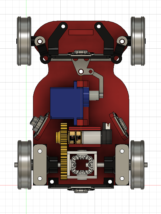
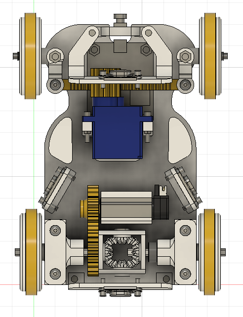
Steering iterations in CAD: v1 Ackermann, v2 Ackermann with a steering rack, v3 parallel rack and pinion (final).
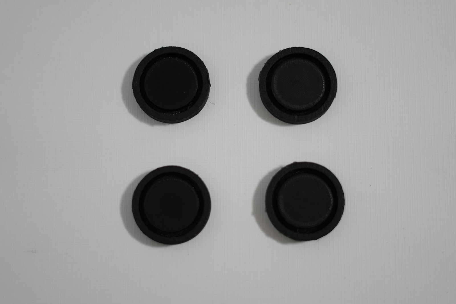
**Final mechanism (v3):** the MG90 servo turns a **12-tooth pinion with module 1 mm**, which moves a **module 1 mm rack** that pushes both steering knuckles together (parallel steering). - **Geometry:** the pitch diameter of the pinion is m Γ— z = 1 Γ— 12 = **12 mm**, so each degree of servo rotation moves the rack Ο€ Γ— 12 / 360 β‰ˆ **0.105 mm**. The relation between servo angle and rack position is linear and has no dead zone, so the angle we command is the angle we get. - **Why we left Ackermann:** in theory Ackermann is better, because the inner wheel turns more than the outer one and neither tyre slips. In practice our Ackermann linkages (v1 and v2) had too many printed joints and too much friction: the servo could not complete its travel (journal Problem 29) and **three servos were damaged** pushing against the linkage (journal Problems 17 and 33). - **Trade-off we accepted:** with parallel steering both front wheels turn the same angle, so in a turn the inner wheel slips a little. On a 270 g car at 0.3–0.6 m/s that slip is small, and the 1 : 1 differential at the rear already removes the larger scrubbing of the driven wheels. We traded a small geometric error for a mechanism that is **reliable, easy to print and does not break servos**. - **Servo mount:** the servo bracket of v3 holds the servo with screws, so its case cannot move (the problem of the first SG90 mount, journal Problem 8). Centre and limits are always **measured, not assumed**, with `servo_calibration` after any mechanical change (on v3: centre 120Β°, left limit 180Β°, right limit 50Β°, provisional). ### 5.4 Wheels and tyres The four 36 mm hubs are printed, and the **tyres are cast on them with C25 silicone rubber** in printed moulds (β‰ˆ 41 mm outside diameter). Silicone grips the field mat much better than printed plastic, which reduces slipping when the car accelerates, brakes and turns, so the gyro turns and the wall distances stay accurate (and, once used, the encoder distance). | Moulds | Mix | Pour | Result | |---|---|---|---| | | | | | Recipe: **30 g of part A + 23 drops of part B**, from the formula **B = ΒΎ Β· A** (drops of catalyst per gram of base), mixed until most bubbles are gone, poured and cured **5–6 hours**. Using a fixed formula makes every batch cure the same, so the four tyres have the same hardness. Full step-by-step with photos: [models/README.md Β§4](models/README.md#4-custom-silicone-tyres). ### 5.5 Iterations that changed the mechanics | Version | Change | Reason (data / test) | |---|---|---| | Chassis 1 β†’ 2 | Side TOF sensors raised **1.5 cm** | The beam passed over the 10 cm wall and read the far side of the field (journal Problem 16). After the change the walls are detected reliably | | Chassis 1 β†’ 2 | SG90 β†’ MG90 servo | Servo moved inside its mount (journal Problem 8) | | v1 β†’ v2 | Ackermann with tie rods β†’ Ackermann driven by a steering rack | Goal: move both wheels from one part (the rack) instead of two separate tie rods. It did not remove the friction of the Ackermann arms (journal Problems 29, 33), which led to v3 | | v2 β†’ v3 | Ackermann β†’ **parallel rack and pinion** (12 teeth, module 1 mm) | The linkage was too tight; three servos were damaged (journal Problems 17, 29, 33) | | v2 β†’ v3 | Tolerances corrected in the CAD | Moving parts were either loose or stuck | | v2 β†’ v3 | Sizes adapted in the CAD instead of improvised fixes; new camera and servo mounts | v2 needed hand adaptations and tape | | v2 β†’ v3 | Tape removed, every joint screwed | Tape showed the design was not complete and let the geometry change | | Printed β†’ cast | Silicone tyres | More grip on the mat; repeatable recipe |

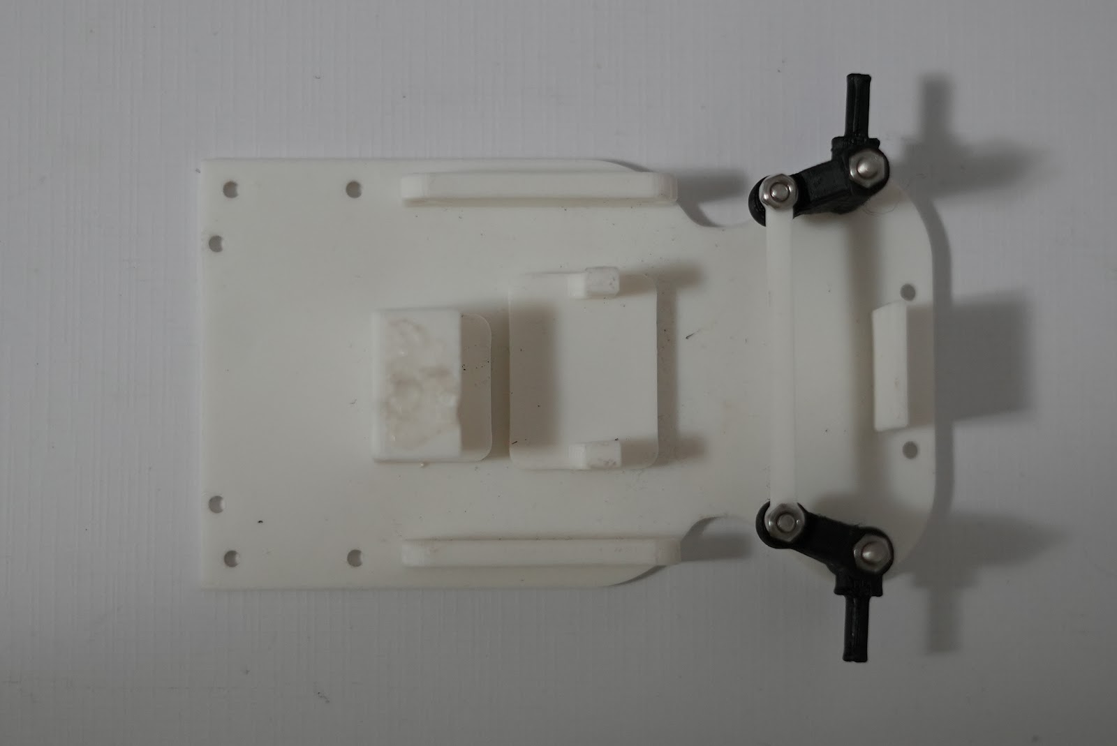
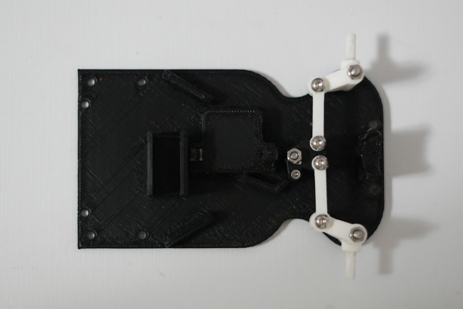
Printed chassis v1, v2 and v3.
--- ## 6. Power and sensor architecture The full electrical documentation is in [schemes/README.md](schemes/README.md): schematic, wiring diagram, BOM with the reason for every component, power budget, PCB manufacturing and datasheets. ### 6.1 Power ``` 3S HV LiPo 11.4 V ──[switch]──┬──► TB6612FNG ──► N20 drive motor β”œβ”€β”€β–Ί Arduino Nano (VIN) ──► 3.3 V pin ──► 4 Γ— TOF400C └──► CN3903 buck 5 V / 3 A ──► camera board, BMI160, servo, encoder ``` | | Typical | Peak | |---|---|---| | Current from the battery | β‰ˆ 0.22 A | β‰ˆ 0.96 A | | Power | β‰ˆ 2.5 W | β‰ˆ 11.0 W | | Run time on one charge | β‰ˆ 1.4 h | β‰ˆ 19 min | The motor uses the battery voltage directly (it is a 12 V motor); everything else uses a **switching** 5 V regulator, because a linear one would waste more power as heat than all the electronics consume. The 3 A buck has a wide margin over the ~1 A peak of the 5 V rail, so a servo stall cannot reset the camera. **The TOF sensors take 3.3 V from the Nano**, not from the 5 V buck rail. Their laser pulses are then on a different rail from the servo, so a servo current peak cannot disturb a distance reading. The cost: four sensors peak near 80 mA, which is more than the small 3.3 V regulator of a classic Nano is rated for. We check the 3.3 V pin with a multimeter while all four sensors are ranging; if it sags, the TOF400C modules can go back to the 5 V rail with no other change (they accept 3.3–5 V). Full budget and failure analysis: [schemes/README.md Β§4](schemes/README.md#4-power-system). ### 6.2 Wiring / pin map (Arduino Nano) The PCB was designed for the Nano ESP32; after that board was damaged (journal Problem 31) we use a **classic Arduino Nano (ATmega328P)**, which has the same pin positions, so the PCB did not change. | Device | Signal | Pin | |---|---|---| | Camera board | UART RX / TX | D0 / D1 | | Encoder | C1 / C2 | D3 / D2 | | TB6612FNG | PWMA / AIN1 / AIN2 | D6 / D7 / D8 | | TB6612FNG | STBY | tied to +5 V on the PCB (always enabled) | | Steering servo | Signal | D9 | | Start button | Input | D10 | | IΒ²C bus (4 Γ— TOF + BMI160) | SDA / SCL | A4 / A5 | | TOF BACK / FRONT / RIGHT / LEFT | XSHUT | A0 / A1 / A2 / A3 | All four TOF sensors share one IΒ²C bus with the gyroscope. At start-up every sensor is switched off with its XSHUT pin, then switched on one at a time and given its own address (LEFT 0x30, RIGHT 0x31, BACK 0x32, FRONT 0x33). **ESP32-S3-CAM** (camera pins = ESP32S3_EYE layout): SDA 4, SCL 5, XCLK 15, VSYNC 6, HREF 7, PCLK 13, Y2–Y9 = 11, 9, 8, 10, 12, 18, 17, 16. UART to the Nano on GPIO43 / GPIO44. ### 6.3 Sensors: selection, placement and calibration | Sensor | Placement | Why | |---|---|---| | **TOF FRONT** | Front centre | Safety brake if a wall is too close in any phase; FRONT vs BACK check after the first turn; parking later | | **TOF LEFT / RIGHT** | Both sides, **straight (0Β°), facing the wall squarely**, centre at ~5 cm from the floor (half of the 10 cm wall), level | Distance to the wall being followed; when the wall ends, the readings become invalid β†’ corner. We first angled them 30Β° forward to see corners earlier, but on the black wall the angled beam returned almost no light (journal Phase 10) | | **TOF BACK** | Rear centre | FRONT vs BACK check after the first turn: after a correct turn the back faces the near outer wall of the corner and the front the long straight | | **BMI160** | Flat on the PCB | Yaw (Z axis) for straight driving and exact 90Β° turns | | **Camera** | Front, slightly down | Sees the pillars of the next section | **Why TOF and not infrared or ultrasonic:** our first sensors were Sharp infrared sensors. Their output is non-linear, so noise grows with distance, and our tests showed they were unreliable beyond 50–60 cm, less than one corridor width (journal Problem 3). We also proved that the standard deviation of their readings could not tell a wall from an open side (journal Problem 2). Ultrasonic sensors have a wide cone that sees the floor and the neighbouring walls. The VL53L1X measures up to 4 m and lets us narrow its measurement area (ROI) in software. **Calibration** - **TOF ROI chosen by experiment, twice.** First (journal Β§8.2) we chose ROI 1 Γ— 6 because it gave the biggest difference between "wall" and "no wall". Later tests with a tape measure (journal Phase 10) showed that with the sensor at 30Β° on the black wall it read **~2 m at every distance** (30, 40, 50, 60 cm and no wall) β€” the difference was real, but the distance was not. With the sensor **straight** and **ROI 16 Γ— 8**, the black wall at 40 cm reads 38.1 cm, 30/30 valid readings, spread < 1 cm. Reliable range: about 45 cm. | Black wall at 30 cm | ROI 1Γ—6 | ROI 8Γ—8 | ROI 16Γ—16 | |---|---|---|---| | Sensor at 30Β° | ~198 cm βœ— | ~112 cm βœ— | invalid | | Sensor at 30Β°, white sheet on the wall (control) | invalid (33 ms) / 35.6 βœ“ (50 ms) | 34.4 βœ“ | 35.4 βœ“ | | **Sensor straight** | invalid | 33.4 βœ“ (50 ms) | **32.0 βœ“** | - **Only "range valid" readings are used.** "Signal fail" readings gave believable but wrong numbers (e.g. 63 cm with the wall at 30 cm). - **Gyroscope:** 1000 samples (β‰ˆ 3 s) at rest right after power-on, while the car waits for the start button; their mean is the offset. Scale checked with 4 hand turns (1440Β°) against a wall β†’ `YAW_SCALE` (Β§10.4). - **Steering:** centre and limits found with the interactive `servo_calibration` sketch, with 2–3Β° of margin before each mechanical stop. - **Camera colours:** HSV thresholds tuned live under the real lighting with Pillar Vision Lab (section 9). **Noise and interference we considered:** sunlight and strong lamps raise the TOF ambient-light level (we print the ambient value in the diagnostic sketch); dark walls return little light, and almost none when the beam hits them at an angle (journal Phase 10), so the side sensors face the wall squarely and "signal fail" readings are ignored; objects outside the field (people, flags) can look like pillars to the camera, so only a horizontal band of the image is searched. --- ## 7. Software architecture ### 7.1 Two boards, each doing what it is best at ```mermaid flowchart LR subgraph CAM["ESP32-S3-CAM β€” vision"] A[OV2640
320Γ—240 RGB565] --> B[HSV colour
classification] B --> C[BFS blob search
+ front-pillar split] C --> D[Closest pillar in cm
+ floor lines] end subgraph NANO["Arduino Nano β€” control"] E[4 Γ— TOF
distances] --> H[State machine] F[BMI160
heading] --> H G[Encoder
distance] --> H H --> I[Steering servo D9] H --> J[Motor via TB6612FNG] end D -- "UART: a few bytes per frame" --> H ``` - **Camera board:** all image processing. It sends one short text line per picture (colour of the closest pillar, its distance ahead and to the side in cm, and where the orange and blue floor lines are), so the link stays fast. - **Arduino Nano:** sensors, control loops and actuators. It never processes images, so its loop timing stays fast and predictable. ### 7.2 Modules | Module | Board | What it does | Code | |---|---|---|---| | TOF driver | Nano | Address assignment through XSHUT (unique IΒ²C address per sensor), continuous ranging, ROI 16 Γ— 8, only "range valid" readings (the driving code uses Long mode; the sensor test uses Short mode β€” with a useful range of only ~45 cm on the black wall, Short mode, which the datasheet gives as more robust to ambient light, will be compared in the next test) | [`tof_gyro_sensors_test`](src/hardware-tests/tof_gyro_sensors_test) | | Gyro driver | Nano | BMI160 read through IΒ²C registers (no library), offset calibration, yaw integration (`yaw += rate Γ— dt`) | [`tof_gyro_sensors_test`](src/hardware-tests/tof_gyro_sensors_test) | | Motor control | Nano | TB6612FNG forward / reverse / coast / short brake with PWM | [`rear_motor_loop_test`](src/hardware-tests/rear_motor_loop_test) | | Steering | Nano | `Servo.h` on the classic Nano (500–2500 Β΅s at 50 Hz); on the Nano ESP32 the pulse was generated by hand. Calibrated centre and limits | [`servo_simple`](src/hardware-tests/servo_simple), [`servo_calibration`](src/hardware-tests/servo_calibration), [`servo_only_test`](src/hardware-tests/servo_only_test) | | Wall keeping | Nano | PID that keeps the start distances to both walls, or to the nearest wall | [`wall_keep_both_pid`](src/hardware-tests/wall_keep_both_pid), [`wall_follow_nearest_pid`](src/hardware-tests/wall_follow_nearest_pid) | | First drive test | Nano | Drive straight and brake when the left wall ends | [`drive_until_left_open`](src/hardware-tests/drive_until_left_open) | | Pillar detection | Camera | HSV β†’ blobs β†’ closest pillar β†’ side to pass; streams picture and mask over USB | [`pillar_viewer.ino`](src/obstacle-challenge/pillar_viewer) | | Obstacle vision v3 | Camera | Locked camera, 4 Γ— 4 blocks, time filter, pillar position in cm (Β§9.3), red / magenta vote, orange and blue lines with the long-and-thin test and the centre-row fit (Β§9.6); 14-field message to the Nano | [`obstacle_camera`](src/obstacle-challenge/obstacle_camera) | | Straight with pillars | Nano | Odometry map (encoder + gyro), pillars on the map, lateral goal β†’ heading β†’ gyro PD (Β§9.4–9.5) | [`straight_pillars`](src/obstacle-challenge/straight_pillars) | | Line test | Nano | Motor off; prints what the camera says about the lines and the pillar, used to measure the row β†’ cm table | [`line_test`](src/obstacle-challenge/line_test) | | Pillar Vision Lab | PC browser | Shows what the camera sees, runs the same algorithm in JavaScript and checks it matches, live parameter tuning | [`viewer.html`](src/obstacle-challenge/pillar_viewer/viewer.html) | | Scenario Roulette | PC browser | Draws valid official track layouts to test on and scores Open Challenge attempts | [`index.html`](src/tools/scenario-roulette/index.html) | **Why we wrote our own drivers:** the BMI160 library we tried only returned zeros without reporting any error (journal Problem 14), and the servo libraries did not work with the Nano ESP32 core (journal Problem 6; on the classic Nano the standard `Servo.h` works). Our register-level and hand-pulse versions are short, fully understood and faster. **Why our own vision code instead of OpenCV:** OpenCV does not run on a microcontroller without an operating system; a Raspberry Pi would add weight, a second battery and a long boot time to a 30 Γ— 20 cm car; and colour detection does not need a neural network. Our pipeline runs at ~25 fps and was verified pixel by pixel against its JavaScript copy. The full comparison (OpenMV, Pixy2, HuskyLens, Raspberry Pi) is in [journal Β§6.2](docs/ENGINEERING_JOURNAL.md#62-why-we-wrote-the-vision-ourselves-instead-of-using-opencv). --- ## 8. Open Challenge strategy ### 8.1 Idea **Finish the three laps safely first, then go faster.** The car drives along a side wall with a two-loop controller (wall distance β†’ small target heading β†’ gyroscope β†’ steering). At the first corner it finds which side opens and fixes the direction of the round. At every corner it turns exactly 90Β° with the gyroscope, and at every straight the wall itself corrects the heading, so small errors cannot add up over 12 corners. After the last corner it drives a short straight and brakes actively. How we got here: a sudden-jump detector (Sharp sensors, journal Β§2.4) β†’ keeping both start distances (Β§4.2) β†’ smooth gyro wall following (Phase 8) β†’ one complete corner and the loop (Phase 9) β†’ **simpler decisions once the sensor data became trustworthy** (Phase 10). ### 8.2 State machine ```mermaid stateDiagram-v2 [*] --> WAITING WAITING --> FIRST_STRAIGHT: start button, gyro calibrated FIRST_STRAIGHT --> DECIDE: one side becomes NO WALL, or time is up DECIDE --> DECIDE: NOT SURE, stop and measure again DECIDE --> FIRST_TURN: side chosen FIRST_TURN --> CHECK: 90 deg turned CHECK --> FIRST_TURN: BACK farther than FRONT, undo and turn other side CHECK --> FOLLOW_WALL: turn correct, direction fixed FOLLOW_WALL --> TURN: followed wall becomes NO WALL TURN --> FOLLOW_WALL: 90 deg turned, turns below 12 TURN --> FINAL_STRAIGHT: 12 turns FOLLOW_WALL --> SAFE_STOP: front too close or timeout FINAL_STRAIGHT --> FINISHED: short time driven FINISHED --> [*]: active brake SAFE_STOP --> [*]: active brake ``` | State | What the car does | |---|---| | **WAITING** | Calibrates the gyroscope at rest (offset), waits for the start button | | **FIRST_STRAIGHT** | Gyro wall following on the nearest wall. Keeps a window of the last readings of each side to see which side opens | | **DECIDE** | Car **stopped**. Turn side = the side that became NO WALL. If the readings are NOT SURE, it measures again with the car still instead of guessing | | **FIRST_TURN / CHECK** | 90Β° gyro turn. Then FRONT vs BACK: if the back is clearly farther than the front, the turn was wrong β†’ undo it and turn to the other side. Only done once; the direction is fixed for the round | | **FOLLOW_WALL** | Follows the **inner wall** at a target distance inside the sensor's reliable range, with the cascade controller. While on target and parallel, it stores the yaw as the real direction of this wall | | **TURN** | Drives straight a short time after the wall ends, then turns 90Β° from the corrected heading (wall direction + 90Β°) | | **FINAL_STRAIGHT β†’ FINISHED** | After 12 turns: straight for a tuned time with the gyroscope, then active brake (both TB6612FNG inputs HIGH) | | **SAFE_STOP** | Any safety rule (8.5) brakes the car instead of letting it drive blind | ### 8.3 Wall or no wall: how the side sensors are read The side TOF sensors face the wall squarely and use ROI 16 Γ— 8 (journal Phase 10). On the black wall each reading is either accurate or invalid, so the car does not try to measure distances it cannot see: | Reading | Meaning | |---|---| | "Range valid" and ≀ 550 mm | **WALL**, distance reliable (Β±1–2 cm) | | Anything else | **NO WALL** β€” the number is never used | Decisions use the last **8** readings: **6 or more** WALL β†’ WALL (distance = median); **2 or fewer** β†’ NO WALL; **3–5** β†’ NOT SURE (no decision yet). The thresholds are provisional and will be confirmed after remounting the sensors (30, 45, 60 cm test). This made the algorithm **simpler**: no 2400–2600 mm "opening" threshold, no comparison of two noisy averages at ~2 m, no 165–185 cm close / far threshold, no jump threshold. The opening is the side without a wall; the corner is the moment the followed wall disappears. ### 8.4 Turning, and why errors do not add up - The turn ends when the gyroscope says **90Β°**, not after a fixed time: a timed turn would change with battery voltage and speed. The wheels straighten gradually near the end (PD on the yaw) and the car brakes a few degrees early to absorb inertia (validated in `turn_left_90_pid_brake`). - Using `previous heading + 90Β°` let a gyro scale error of ~1.5Β° per turn grow past what the wall controller could correct (Β±8Β°) after about 6 turns, and the car hit the inner wall in a later lap (journal Problem 43). Now **the wall is the reference**: while the car is on target and the distance is not changing, its yaw is the true direction of the wall, and the next turn starts from it. Every straight is a fresh start. ### 8.5 Safety rules (always active) Our priority is to **complete the three laps and stop correctly** β€” a crash loses the laps, a slower run only loses seconds. | Rule | Why | |---|---| | NOT SURE β†’ slow down or stop and measure again | A wrong turn side ends the run; waiting costs a second | | Turn-side decision with the car **still**, using medians | Readings in motion and single readings were the cause of wrong decisions | | FRONT safety in every phase, independent of the BACK sensor | Last line of defence against hitting a wall | | FRONT/BACK check and undo after the first turn | A wrong first turn is corrected instead of followed | | Timeout for every straight and phase | The car never drives blind if a reading never comes | | Lower speed after turns and during decisions | More valid readings before the next decision | | Wall corrects the heading every straight | A small gyro error cannot become a crash in lap 3 | | Motor only forward during a run (except the controlled undo), active brake at the end | Drive gear skips on sudden reverse (journal Problem 34) | ### 8.6 Edge cases | Case | Handling | |---|---| | Car starts at any position inside the starting section | Gyro wall following on the nearest wall; nothing about the position is assumed | | Inner wall far away (100 cm corridor) | Its readings are invalid (NO WALL); after the turn the car deviates toward it until it is in range, then follows it | | Right after a turn, the sensor sees the tip of the inner wall diagonally | Close / far is decided only 1 s after the turn (`SW_MIN_MS = 1000`, journal Problem 44) | | A single bad reading | Window of 8 readings with a NOT SURE band | | Gyro drift over 3 laps | Calibration at rest before every run + wall re-alignment every straight | | Wrong first turn | FRONT/BACK check and undo | | Narrow corridor (600 mm) | The inner wall is close, its readings are valid from the start; the car follows it directly | | Never touch the outer wall (rule 9.18) | The car always follows the **inner** wall at a short distance, and the FRONT safety brakes before any wall | | Wrong first turn | Undo is a short reverse inside the corner section, which the rules allow (Appendix A.4) | | Stopping inside the starting section | After exactly **12** turns (3 laps Γ— 4 corners) a tuned final straight and active brake held forever. A 13th turn would carry the car out of the starting section and lose the 3 stop points (rule 9.24.3) | ### 8.7 Next version: decision tree with encoder delays (planned 25 October) This is the algorithm we will build next. It keeps everything validated above (cascade controller, 90Β° gyro turn, active brake, WALL / NO WALL / NOT SURE window) and replaces the **timed** waits with **encoder distance**, because time-based waits changed with battery voltage (the car behaved differently on USB than on battery). ``` START β”‚ calibrate gyroscope β†’ wait for start button β–Ό ══════════ PHASE 1: FIRST STRAIGHT (direction unknown) ══════════ β”‚ β”œβ”€ Follow the NEAREST wall (PID + gyroscope) β”‚ └─ Opening detected on one side? β”œβ”€ NO β†’ keep driving └─ YES β†’ store that side as the TURN DIRECTION (fixed for the round) β”‚ β–Ό Delay: N encoder turns β”‚ β–Ό TURN toward that side until 90Β° (gyroscope) counter = 1 β”‚ β–Ό ══════════ PHASE 2: FIND THE INNER WALL ══════════ β”‚ β”œβ”€ Follow the OUTER wall (PID + gyroscope) β”‚ └─ Inner wall detected? β”œβ”€ NO β†’ keep following the outer wall └─ YES β†’ enable the opening search β”‚ β–Ό ══════════ PHASE 3: LOOP (always the same from here) ══════════ β”‚ β”œβ”€ Follow the INNER wall (PID + gyroscope) β”‚ └─ Opening detected on the inner side? β”œβ”€ NO β†’ keep following the inner wall └─ YES β”‚ β–Ό Delay: N encoder turns β”‚ β–Ό TURN toward the stored direction until 90Β° counter++ β”‚ β–Ό counter == 12? β”œβ”€ YES β†’ FINISH β”‚ drive X encoder turns β†’ active brake β†’ stay still β”‚ └─ NO β†’ drive M encoder turns, NOT searching for openings β”‚ β–Ό back to "Follow the INNER wall" ``` | Element | Why | |---|---| | Delays measured in **encoder turns**, not milliseconds | Distance does not depend on battery voltage; a timed delay did | | During both delays the car holds the **gyro heading** only | No wall is available there; with 1Β° of gyro error the car moves only ~3.5 mm sideways over 200 mm | | **M** turns after every turn without searching for openings | Right after the turn the inner side sees the corner, which looks like an opening (journal Problem 44); M must be long enough to leave the corner section | | Outer wall followed **only** in Phase 2 | After the first corner the car is always close to the inner wall, so it never needs the outer wall again | | Exactly **12** turns, then X encoder turns and brake | Stops inside the starting section (rule 9.24.2); a 13th turn would leave it (rule 9.24.3) | | Opening = the WALL / NO WALL / NOT SURE window of 8 valid readings (Β§8.3) | Single readings on the black wall caused wrong decisions (journal Problem 46) | **To measure before coding:** encoder ticks per millimetre (push the car exactly 1 m), the steering turning radius at full lock, and where the opening appears for a 1000 mm and a 600 mm next corridor. With the side sensors reliable only up to ~45 cm (journal Β§12.4), Phase 2 must also be checked in a 1000 mm corridor, where the outer wall may be out of range right after the first turn β€” in that case the car holds the gyro heading until a wall is valid. --- ## 9. Obstacle Challenge strategy ### 9.1 Idea The camera does not only say *"there is a red pillar on the left"*: it measures **where the pillar is in centimetres** (how far ahead and how far to the side). The Nano keeps a small **map of the current straight**, built with the encoder (distance) and the gyroscope (heading), and puts every pillar on that map. The car then steers toward a lateral position that leaves the pillar on its correct side, with the same gyro PD that drives the Open Challenge straights. The floor lines are measured the same way and will also be put on the map, so the car knows where the corner is even after the line leaves the picture. | Stage | Status | |---|---| | Vision: pillars, magenta parking walls, orange and blue lines | βœ… `obstacle_camera` v3 | | One straight with pillars (map + steering law) | βœ… Validated 27 Oct: every case passes ([`straight_pillars`](src/obstacle-challenge/straight_pillars)) | | Floor lines measured in cm | βœ… Row β†’ cm formula measured 27 Oct (error ≀ 1 cm) | | Corners, laps, stop in the starting section | ⏳ Next (plan in Β§9.7 and Β§9.10) | | Parking | 🧠 Being designed (Β§9.8) | **Why we left the "correct third" rule** (our first plan, 7 Oct): a rule that only looks at the picture has no information once the pillar leaves it. A pillar passed at the safe distance disappears from the picture **15 cm before** the car reaches it (measured), and in the first driving test (`obstacle_first_test`, 26 Oct) the car reacted to pillars too late. With a map, the pillar is still known while it is out of the picture, and the car can plan *how much* to move instead of only *which way*. The full story is in [journal Phase 11](docs/ENGINEERING_JOURNAL.md#13-phase-11--obstacle-challenge-from-pixels-to-centimetres-2627-october-2026). Every formula of this section is explained from the beginning, with worked examples, in [journal Β§13.3 "The math, step by step"](docs/ENGINEERING_JOURNAL.md#133-the-math-step-by-step). ### 9.2 Vision pipeline (camera board, `obstacle_camera` v3.1) 1. **Picture:** 320 Γ— 240 RGB565, ~12.5 fps with pillars and lines. Only rows 124–239 are processed (the floor and the pillars; above is the room). 2. **Frozen camera:** 5 s after power on, white balance, exposure and gain are locked, so the colour of a pillar does not change when the scene changes (red was flickering much more than green before the lock). 3. **HSV classification**, tested in this order: red β†’ green β†’ magenta β†’ orange β†’ blue. Values measured with the camera locked: | Colour | Hue | Saturation | Value | Measured / why | |---|---|---|---|---| | πŸŸ₯ Red pillar | 345–26Β° (wraps) | β‰₯ 115 | β‰₯ 95 | Pillar H 15–23Β° | | 🟩 Green pillar | 82–150Β° | β‰₯ 150 | β‰₯ 90 | Pillar H 86–95Β°, S β‰₯ 152; the yellow-green floor has S 88–156 | | πŸŸͺ Magenta wall | 328–353Β° | β‰₯ 84 | β‰₯ 84 | Very close to red (see step 4) | | 🟧 Orange line | 29–52Β° | β‰₯ 115 | β‰₯ 110 | Line H 32–44Β°, S 131–173; red pillar H 4–22Β°, floor starts at 60Β° | | 🟦 Blue line | **110**–200Β° | **30–120** | β‰₯ 65 | The locked camera sees the blue line as dark grey-teal (H ~160Β°, S 46–113). The floor next to the car reaches H 85Β° (shadow + lens), so blue starts at 110Β° (it started at 85Β° and the floor became a false blue line, 28 Oct). The **maximum** saturation keeps the green pillar (S β‰₯ 152) out | 4. **Red or magenta?** Red and magenta pixels that touch are grouped; if β‰₯ 70 % of the group is magenta, the whole group is a parking wall and never a pillar (a shape filter failed for this). 5. **Pillars:** only rows 126–207 are searched (above: things outside the field; below: too close to measure). Pixels are grouped in **4 Γ— 4 blocks** (a block is red/green if β‰₯ 12 of its 16 pixels are), blobs are found with a BFS, touching pillars are split (the front one is kept), and a blob must be a **solid** chunk (β‰₯ 75 % filled), not touch the picture edge and be at a possible distance (5–130 cm ahead, ≀ 70 cm to the side). 6. **Time filter:** a pillar is reported when it is seen in 2 of the last 4 pictures and dropped after 3 empty ones. 7. **Floor lines:** see Β§9.6. 8. **Message to the Nano** (UART, 115200 baud, one text line per picture): ``` $color,x,bottom,correct,blueFound,blueRow,seq,width,distCm,latCm,orangeFound,orangeRow,blueCenterRow,orangeCenterRow ``` The first 10 fields are the pillar (colour, centre `x` in px, width in px, `distCm` ahead and `latCm` to the side); the last 4 are the lines (v3). Older Nano sketches read only the first 10 fields, so they keep working. ### 9.3 From pixels to centimetres: where is the pillar? The camera works like a **pinhole camera**: an object of real size *S* at distance *D* looks *f Β· S / D* pixels wide, where *f* is the focal length in pixels. A pillar is 5 cm wide, so its width in the picture gives its distance. ``` xc = x βˆ’ X_CENTER_OFFSET pixels from the real straight-ahead line a = atan(|xc| / f) angle between the car's direction and the pillar seen = 5 cm Β· (cos a + sin a) width of the pillar as seen from that angle ahead = f Β· seen / width cm ahead of the camera (to the front face) side = ahead Β· xc / f cm to the side (+ right, βˆ’ left) ``` - **Why `cos a + sin a`:** the pillar is a 5 Γ— 5 cm square. Seen straight on, only its front face shows (5 cm). Seen from an angle *a*, two faces show, and together they look 5 Β· (cos *a* + sin *a*) cm wide (up to 7.1 cm at 45Β°). Without this, pillars to the side would look closer than they are. - **`X_CENTER_OFFSET = 12 px`:** a pillar exactly in front of the car appeared 12 px to the right of the picture centre, because the camera is turned about atan(12 / 100) β‰ˆ 7Β°. All positions are measured from that real centre line. - **`f = FOCAL_PX = 100`:** measured with `straight_measure`. With 112, a centred pillar at 30 cm read 35 cm and at 50 cm read 59 cm; with the pillar 16.75 cm to the side at 50 cm it read 51 cm and Β±18 cm (symmetric). 100 is the value that fits all the measurements best. - **Range:** about 50 cm ahead (limited by the top of the search band, which we keep to avoid the background). A pillar passed at the safe distance leaves the picture through its side 15 cm before the car; a centred pillar is seen down to 3 cm. **Example:** a red pillar 20 px wide with its centre at x = +40 px β†’ xc = 28 px, a = 15.6Β°, seen = 5 Β· (0.963 + 0.269) = 6.2 cm, ahead = 100 Β· 6.2 / 20 = **31 cm**, side = 31 Β· 28 / 100 = **8.7 cm to the right**. ### 9.4 The map of the straight (odometry) The Nano keeps the position of the camera point on a map of the current straight: **x = cm forward, y = cm to the left** of the lane where the straight started (the "home lane"). ``` ds = new encoder ticks / 15.1 cm driven in this loop h = (yaw before + yaw now) / 2 average heading in this loop carX += ds Β· cos h carY += ds Β· sin h ``` - **15.1 ticks per cm** was measured by pushing the car by hand: 980 ticks = 66 / 65.5 / 63.5 cm (average 65 cm). The first value we used, 19.6, made the map think every distance was **23 % shorter** than it was, and the car reacted late. - **Putting a pillar on the map:** the camera gives `ahead` (front face) and `side`. The pillar centre is `fwd = ahead + 2.5 cm` ahead and `left = βˆ’side` to the left, and in map coordinates: ``` pillarX = carX + fwd Β· cos h βˆ’ left Β· sin h pillarY = carY + fwd Β· sin h + left Β· cos h ``` - **The same pillar seen again** (closer than 15 cm on the map, same colour) is not a new pillar: its stored position moves 30 % toward the new measurement (`BLEND = 0.3`), so the noise of single pictures is averaged out. - The map keeps two pillars: the **current** one (being passed) and the **next** one (already seen farther away). - **The map is the blind zone:** when the camera loses the pillar, its position on the map is still known, so there is no special "blind" state in the code. ### 9.5 How much to move: the steering law **1. Lateral goal.** The pillar centre must stay at least `TARGET_CM = 17 cm` from the car centre = half the car (4.25 cm) + 10 cm of gap + half the pillar (2.5 cm). ``` red (pass on its right): goalY = min(carY, pillarY βˆ’ 17) green (pass on its left): goalY = max(carY, pillarY + 17) ``` The `min` / `max` mean "never move back toward the pillar": if the car is already farther than 17 cm, it stays where it is. **2. Heading toward the goal.** The car must be at the goal lateral position **10 cm before the pillar's front face** (`ARRIVE_BEFORE_CM`): ``` look = max(12 cm, pillarX βˆ’ 2.5 βˆ’ carX βˆ’ 10) heading = atan2(goalY βˆ’ carY, look) limited to Β±45Β° ``` `look` never goes below 12 cm, so the angle does not explode next to the pillar. Β±45Β° is the largest angle that still reached the second pillar in the simulation (35Β° hit it). **3. Gyro PD β†’ wheels** (the same values as the validated Open Challenge code): ``` steering = 2.0 Β· (heading βˆ’ yaw) βˆ’ 0.10 Β· yawRate limited to Β±60Β° of servo, max 300 Β°/s ``` **4. While passing and after the pillar.** - As soon as the camera passes the pillar centre, the car already aims at the **next** pillar (or straightens), but it may not move sideways **toward** the pillar beside it. - 5 cm after the pillar centre (`RETURN_AFTER_CM`) the pillar is cleared: the next pillar becomes the current one, or the car returns to the home lane (`look = 20 cm`). The rear does not swing into the pillar because only the front wheels steer. - In the first version the car drove ~25 cm after a pillar before reacting, and there was no room left for a second pillar 100 cm later; aiming at the next pillar earlier fixed it. **Example:** car at (0, 0), red pillar centre at (40, +10) β†’ goalY = min(0, 10 βˆ’ 17) = βˆ’7 cm, look = 40 βˆ’ 2.5 βˆ’ 0 βˆ’ 10 = 27.5 cm, heading = atan2(βˆ’7, 27.5) = **βˆ’14Β°** (to the right). With yaw = 0 the servo moves 2.0 Β· 14 = 28Β° to the right of centre, and less as the car turns. **Tested:** first in a simulation (car model + camera at 6–10 Hz with 0.2 s delay, Β±10 % distance error, 3 cm noise, speed 20–40 cm/s, pillars at Β±10 cm, two pillars 100 cm apart), then on the track: **every straight-with-pillars case passed on 27 Oct**. Known limit: the car must start straight (5Β° off at the start failed in the simulation). ### 9.6 Floor lines in centimetres (27 October) **Detection** (for each colour, every picture; v3.1, validated 28 Oct): 1. Take the biggest patch of that colour below row `LINE_TOP_ROW = 140`. 2. It must be **long** (diagonal of its box β‰₯ 40 px) and **thin** (pixels Γ· length ≀ 40 px). A pillar or a blob is short and fat; this also rejects the orange edge of a red pillar. 3. **Floor above:** a line is painted *on* the floor, so it has white floor above it. For every column of the patch the camera looks 3–6 rows above its top edge and takes the darkest pixel; the column counts if it is bright (V β‰₯ 130, floor V 128–220). At least 60 % of the columns must count. The bottom edge of the black wall is also a thin dark stripe β€” far away it is indistinguishable from a blue line by colour β€” but it has **dark wall above**, so it is rejected (`no (wall above)`). This does not depend on the light, because the floor and the line change together. 4. **Row straight ahead:** the lowest row of the patch in the 20 centre columns (x = 172 Β± 10). (A least-squares fit over wider columns was tried on 28 Oct; together with lower size minimums and joining aligned pieces it let floor shadows in, so it was dropped β€” see the journal, Problems 59–60.) **Range measured on the car (28 Oct):** orange line from **16 cm** (row 144), blue line from **9 cm** (row 155). No false line on the empty floor (3 places) or looking at the black wall. Beyond ~9 cm the blue line becomes a 1–2 px dark streak with coloured fringes: its colour is gone, so it cannot be told from the wall by colour alone. The corner plan only needs each line seen once (it goes on the map), and the two lines of a corner are far apart along the car's path (~71 cm and ~14 cm before the wall ahead, Β§9.7), so seeing them at 9–16 cm is enough to tell which one comes first. **Colour probe:** with `STREAM_TO_PC = false` the status also prints the H, S, V range of two fixed boxes (straight ahead at row 170 β‰ˆ 5 cm, and row 228 at the bottom). Putting a line, a pillar or the floor there gives the exact camera numbers in seconds β€” the way to recalibrate under the competition light. **Row β†’ distance.** Measured on 27 Oct with the line in front of the car (and checked with the car parallel to the wall, as it really arrives at a corner): ``` distance (cm) = 276.2 / (row βˆ’ 129.2) βˆ’ 1.8 ``` | Row | Measured | Formula | |---|---|---| | 192 | 2 cm (parallel to the wall) | 2.6 | | 176 | 5 cm | 4.1 | | 158 | 8 cm (parallel to the wall) | 7.8 | | 153 | 10 cm | 9.8 | | 145 | 15–16 cm | 15.7 | | 143 | 18 cm | 18.3 | | 141 | 22 cm | 21.7 | This is the ground-plane perspective of a low camera: row 129 is the horizon, and the floor gets squeezed into fewer rows the farther it is. **Why the lines are only seen up to ~22 cm:** the camera is very low, so it sees the floor almost edge-on. At 20 cm the 2 cm line is only **2 rows tall** (~100–130 pixels); at 25 cm it has only 22–39 pixels and its colour blends with the floor. This is a physical limit, not a setting: lowering the thresholds further would let the wall edge in, and on an empty floor the camera reports no line (checked). It is enough for the corner plan (Β§9.7); if not, the camera can be raised or tilted later, at the cost of recalibrating the pillars. ### 9.7 Corners and laps (next) **Field geometry** (official mat): both lines of a corner start at the corner of the inner wall and reach the outer wall 42 cm from the corner. For a car in the middle of the corridor, the **first line** crosses its path ~71 cm before the wall ahead and the second ~14 cm before it. If the car is 10 cm off the middle, the first line moves only ~6 cm, so it is a good marker of how far the corner is. **Plan** (steps 3–7 of Β§9.10): 1. **Direction of the round:** the colour of the first line seen at the first corner β€” orange first β†’ clockwise, blue first β†’ counter-clockwise β€” then kept for the whole round. 2. **Line on the map:** the line distance (Β§9.6) is put on the map like a pillar and confirmed by 2 messages that agree within Β±5 cm. A reflection never appears twice at the same place on the floor. 3. **Turn point = line + an offset** that depends on the turning radius (to be measured). The turn starts at a map position, so camera delay and speed do not change it. 4. **90Β° turn while driving** with the gyro PD, toward **absolute headings** (0Β°, 90Β°, 180Β°, 270°…): the error of one turn is corrected on the next straight instead of adding up. Pillars are ignored during the turn; after it, a new map starts and no lines are searched for the next 60 cm (so the second line of the corner is never counted). 5. **Pillars right after the corner:** the first pillar seats of a straight are exactly at its start. The turn must end inside the corner section, so these pillars are 20–40 cm ahead, within the camera's range. 6. **12 corners**, then ~75 cm more with the straight logic and stop inside the starting section. ### 9.8 Parking (planned) After the third lap the car will find the magenta walls of the parking lot (already detected by the camera, not yet sent to the Nano) and park parallel. Starting the round **inside** the parking lot is worth 7 more points. The lot is 1.5 Γ— the car length (β‰ˆ 18 cm for our 12–13 cm car), so parallel parking will almost certainly need **reverse**; the drive gear once skipped on a sudden reverse (journal Problem 34), so the reverse must be gentle and tested first. ### 9.9 Pillar Vision Lab Pillar Vision Lab is the calibration tool we built: a web page that receives every picture over USB (Web Serial), draws the colour mask on top, runs the same algorithm in JavaScript, checks that its result matches the camera board, and lets us tune every parameter live. It turned threshold tuning from guessing into measuring, and we also used it to tune the floor-line colours. ### 9.10 Roadmap to the complete Obstacle Challenge **Points** in one Obstacle round (rules Β§10): sections 24 + laps 3 + stop in the starting section 3 + no pillar moved 10 (8 if moved) + start from the parking lot 7 + parking 15 (7 if partial) = **62**. Three clean laps and a correct stop already give 40. **Time:** a round is 3 minutes and three laps along the middle of the corridor are β‰ˆ 24 m, so the car must average at least ~16–20 cm/s to leave time for parking. | # | Step | Done when | |---|---|---| | 1 | Camera detects both lines (long-and-thin filter) | βœ… 27 Oct | | 2 | Row β†’ cm table, and lines without false detections | βœ… 27–28 Oct (floor-above check, blue from 110Β°; orange from 16 cm, blue from 9 cm) | | 3 | Corner rehearsal by hand (Nano, motor off): map + line + direction + "turn now" | Correct direction and turn point; the second line is never counted | | 4 | Measure the turn while driving (forward and side displacement β†’ radius) | Radius known β†’ turn point computed | | 5 | One corner with the motor: no pillars, then a pillar before and right after the corner | 4 of 5 attempts in each case | | 6 | One full lap (4 corners, absolute headings) | No wall or pillar touched | | 7 | Three laps and stop | Stops inside the starting section | | 8 | Robustness: both directions, different start zones, Scenario Roulette pillar cards | Results table in the journal | | 9 | Speed: fast on free straights, slow near pillars and corners | Three laps in < ~2 min | | 10 | Camera sends the magenta walls to the Nano | β€” | | 11 | Start from inside the parking lot | +7 points | | 12 | Parallel parking after the third lap | +15 points | | 13 | One final Obstacle program, start button, battery only | Same behaviour as on USB | --- ## 10. Systems thinking: constraints, trade-offs and risks ### 10.1 How the subsystems depend on each other | Decision | Affects | Example | |---|---|---| | Camera on its own board | Software, power | Nano loop stays fast; costs ~0.5 W more and a UART link | | PCB as chassis | Mechanics, electronics, time | Very compact and reliable, but every revision takes ~2 weeks to arrive from China | | TOF height on the chassis | Sensors, software | 1.5 cm higher fixed the readings over the wall without any code change | | TOF mounting angle | Sensors, software, strategy | At 30Β° the black wall returned no light and every decision based on it failed; straight sensors made the data trustworthy and the algorithm simpler | | Steering mechanism | Mechanics, electronics, software | Ackermann friction broke three servos; rack and pinion protects the servo and makes angle β†’ wheel position linear | | Car size and mass (13 Γ— 9.5 cm, 270 g) | Mechanics, power, strategy | Light enough for a 1 : 1 drive and a 380 mAh battery; narrow enough to have room on both sides in a 60 cm corridor | | TOF on the Nano's 3.3 V pin | Power, sensors | Isolated from servo peaks, but limited by the Nano's small regulator | | Servo mount angle | Mechanics, software | Steering centre must be measured in software after every mechanical change | | Battery voltage directly to the motor | Power, control | Speed changes as the battery discharges, so turns are controlled by gyro angle, not time | ### 10.2 "We chose X instead of Y because…" | We chose | Instead of | Because (data or test) | |---|---|---| | TOF400C (VL53L1X) | Sharp infrared | Sharp unreliable beyond 50–60 cm in our tests (journal Problem 3) | | Binary "wall / open" and jump detection | Comparing left vs right distances | Comparing magnitudes beyond 50 cm gave false decisions (journal Β§2.3) | | Side TOF **straight (0Β°)** | Angled 30Β° forward to see corners earlier | Black wall at 30 cm: ~198 cm (wrong) at 30Β°, 32.0 cm with 30/30 valid readings straight (journal Phase 10). Correct data over early data | | ROI **16 Γ— 8** | ROI 1 Γ— 6 | 1 Γ— 6 was invalid even on a white sheet; 16 Γ— 8 measured 38.1 cm at 40 cm, spread < 1 cm; 16 Γ— 16 read short because its tall cone sees the floor | | Decide by valid / invalid readings, window of 8 | Distance thresholds at ~2 m | Beyond ~45 cm the black wall gives no valid readings, so "far wall" and "no wall" cannot be told apart by distance | | Wall as heading reference every straight | Gyro-only absolute headings | Gyro scale error (~1.5Β° per turn) exceeded the Β±8Β° the wall controller can correct after ~6 turns (journal Problem 43) | | Moving reference for jump detection | Fixed reference | The fixed version tested worse on the track (journal Problem 4) | | Following the outer wall at its start distance | Centring between the walls | The inner walls move every round, so the centre changes; the outer wall never moves | | Floor lines for corners in the Obstacle Challenge | Side TOF jumps | Pillars near the walls could create false jumps; the lines are fixed by the rules | | Pillar position in cm + odometry map of the straight (27 Oct) | "Correct third" of the image (our 7 Oct plan) | A pillar passed at a safe distance leaves the picture 15 cm before the car reaches it; with only the picture the car reacted too late (first test, 26 Oct). The map keeps the pillar while it is out of sight and says *how much* to move. Every straight-with-pillars case passed on the track | | Floor line measured in cm and stored on the map | Turning when the line leaves the bottom of the picture | Leaving the picture happens only ~3–5 cm ahead, with few pixels, and later at higher speed because the camera message is ~0.2 s old; a map position does not depend on speed or delay | | `BLUE_MAX_SAT = 120` | Only minimum thresholds | The locked camera sees the blue line grey-teal (S 48–103), the same hue as the green pillar (S β‰₯ 152): a maximum saturation separates them | | Our own BMI160 driver | DFRobot library | The library returned only zeros, without errors (journal Problem 14) | | Hand-generated servo pulse (on the Nano ESP32) | ESP32Servo / LEDC | Libraries did not work with that board core (journal Problem 6) | | MG90 metal-gear servo | SG90 | SG90 moved in its mount (journal Problem 8) | | Parallel rack-and-pinion steering | Ackermann linkage | Ackermann friction stopped the servo and damaged three servos (journal Problems 17, 29, 33); the small slip of parallel steering is acceptable at our mass and speed | | 1 : 1 differential | Extra gear reduction | The 270 g car needs only β‰ˆ 8 mNΒ·m at the wheel; 1 : 1 keeps top speed and uses identical, easy-to-print gears | | Cast silicone tyres | Printed or O-ring tyres | More grip on the mat; repeatable recipe (B = ΒΎ A) gives four identical tyres | | Screws on every joint | Tape and hand fixes | Geometry stays the same after crashes and disassembly | | Classic Arduino Nano | New Nano ESP32 | Same footprint (no new PCB); standard `Servo.h` works; available immediately after the ESP32 was damaged | | Own vision on ESP32-S3 | OpenCV on Raspberry Pi, Pixy2, HuskyLens | Weight, boot time, second battery, and we can explain and tune every step (journal Β§6.2) | | Custom PCB | Perforated prototype board | Prototype board too bulky; PCB is cleaner and doubles as the chassis | | Buck converter | Linear regulator | A linear regulator would waste ~3 W as heat | ### 10.3 Risks and mitigation | Risk | Mitigation | |---|---| | Main board damaged by a wrong voltage (journal Problem 31: the Nano ESP32 was lost) | Battery only reaches VIN, VM and the buck; code is uploaded with the battery **off** | | TOF sensors draw more than the Nano's 3.3 V pin can give | Measure the 3.3 V pin under load; fallback: TOF VIN to the 5 V buck rail | | Classic Nano (5 V) TX into the camera's 3.3 V RX | Resistor divider on that line before the camera link is connected | | Servo blocked by the steering mechanism | Rack and pinion with low friction; limits measured with 2–3Β° margin | | Drive gear skips on a sudden reverse (journal Problem 34) | Motor only drives forward during a run; stops with short brake | | IΒ²C bus freezes and hangs the program (journal Problem 12) | `Wire.setTimeOut(50)`; check connectors; each sensor tested alone first | | Loose sensor wire (journal Problem 30) | Locking connectors on the PCB; hardware tests before every session | | Lighting at the venue differs from home | Colour thresholds re-tuned on site with Pillar Vision Lab in minutes | | Camera sees objects outside the field | Search only a horizontal band of the image | | Steering not centred after a mechanical change | Re-run `servo_calibration` after any change to the steering | | Side TOF cannot see the black wall (journal Problem 46) | Sensors straight at ~5 cm, ROI 16 Γ— 8, only "range valid"; re-test with a tape measure after any change to the sensor mounts | | Wrong turn side at the first corner | Decision with the car still, NOT SURE band, FRONT/BACK check and undo | | Gyro error accumulates over 12 turns | Wall re-alignment every straight | | The camera sees the floor lines only up to ~22 cm (low camera) | Lines put on the map and confirmed with 2 messages; if not enough, raise / tilt the camera and recalibrate | | Parallel parking needs reverse, and the drive gear skipped on a sudden reverse | Gentle reverse only, tested alone before the parking manoeuvre | The complete list of the **58 problems** we found, with their causes and solutions, is in [journal Β§15](docs/ENGINEERING_JOURNAL.md#15-summary-of-problems-and-solutions). ### 10.4 Why each setting has its value Every number in the Open Challenge code comes from a measurement, from the field geometry, or from the rules. Values marked *provisional* are confirmed in the next test after the side sensors are remounted. | Setting | Value | Why this value | Evidence | |---|---|---|---| | Side TOF angle | **0Β°** (facing the wall) | At 30Β° the black wall reflects the laser away: a wall at 30 cm read ~198 cm. Straight: 32.0 cm, 30/30 valid | Journal Β§12.3 | | Side TOF height | ~**5 cm** (centre) | Half of the 10 cm wall. With a 16Γ—8 cone (β‰ˆ Β±7Β° vertical) the beam at 50 cm covers β‰ˆ βˆ’1 to +11 cm: almost all on the wall, little floor, nothing over the top | Journal Β§12.4, rule 13.3 (100 mm walls) | | ROI | **16 Γ— 8** | Wide and low: measured 38.1 cm at 40 cm (30/30). 16Γ—16 reads short (floor in the cone), 1Γ—6 is invalid even on white | Journal Β§12.4 | | Timing budget | **50 ms** (*provisional*; 100 / 140 ms to be tested) | 33 ms gave invalid readings with narrow ROIs; more time = more light but fewer readings per second | Journal Β§12.2–12.4 | | Readings used | only **"range valid"** | "Signal fail" gave believable wrong numbers (63 cm at 30 cm, 65.5 cm at 80 cm) | Journal Β§12.3–12.4 | | `WALL_MAX_MM` | **550 mm** (*provisional*) | 100 % valid at 400 mm, 0–27 % at 600 mm: the cut goes between | Journal Β§12.6 | | Decision window | **8 readings: β‰₯ 6 WALL, ≀ 2 NO WALL, else NOT SURE** | Wall at 40 cm: 30/30 valid; no wall: 0/30; 60 cm: 0–27 %. The NOT SURE band avoids guessing on the edge | Journal Β§12.6 | | Target distance to the inner wall | **β‰ˆ 250 mm** (*provisional*; before: 600 mm) | 600 mm was outside the sensor's reliable range (~450 mm). In a 600 mm corridor, 250 mm from the inner wall puts the 95 mm-wide car roughly in the middle and leaves β‰₯ 155 mm to the outer wall even with the βˆ’100 mm tolerance of the International Final (rule 9.18: never touch the outer wall). In a 1000 mm corridor the car simply stays close to the inner wall, still far from the outer one | Rules 8 and 9.18, journal Β§12.4 | | Max lean while following the wall | **5–8Β°** | A small tilt keeps the side beam almost perpendicular to the wall (a tilt of 8Β° changes the reading by only 1 %). Bigger tilts made the sensor read diagonally (journal Problem 36) and, on a black wall, an angled beam loses its signal (journal Β§12.3) | Journal Problems 36, 38, Β§12.3 | | Heading re-alignment limit | **Β±8Β° per straight** | Same as the largest lean the wall controller can command; a bigger difference means the estimate is wrong (e.g. measured near a corner), so it is ignored | Journal Problem 43 | | Gyro range / rate | **Β±500 Β°/s, 400 Hz** | A 90Β° turn takes about 1 s (β‰ˆ 90–150 Β°/s peak), so Β±500 Β°/s never saturates and gives 4Γ— the resolution of Β±2000 Β°/s (65.6 vs 16.4 LSB per Β°/s). 400 Hz integrates the yaw in small steps | `turn_left_90_pid_brake` final-angle print | | Gyro calibration | **1000 samples (β‰ˆ 3 s) at rest** (competition value; the first wall-following sketch used 300) | Averaging more samples makes the offset more exact. It runs right after the power switch, while the car waits for the start button (rule 9.11), so it costs no race time and needs no input from the team (rule 9.9) | Rules 9.9, 9.11 | | `YAW_SCALE` | measured: 4 hand turns (1440Β°) against a wall, `YAW_SCALE = 1440 / measured` | Corrects a gyro that reads a few % short or long, the error behind Problem 43 | Journal Problem 43 | | Turn end | **90Β° by gyroscope**, brake `STOP_LEAD_DEG = 2Β°` early, slow in the last 25Β° | A turn by time changes with battery voltage; braking early absorbs the car's inertia. Values tuned with the printed final error | `turn_left_90_pid_brake` | | Close / far decision after a turn | **1 s after the turn** (`SW_MIN_MS = 1000`) | Earlier, the sensor sees the tip of the inner wall diagonally; at 1 s it chose correctly almost every time | Journal Problem 44 | | Straight after the wall ends, before turning | **500 ms** (*to be replaced by a distance*) | The side sensor is near the middle of the car; the rear must clear the inner corner before turning. At 0.3–0.5 m/s, 500 ms β‰ˆ 15–25 cm, more than the 13 cm car length. A distance from the encoder would not depend on speed or battery | Car length, journal Β§11.2 | | Speed | ≀ β‰ˆ **0.4 m/s** while deciding | One decision needs 8 readings Γ— 50 ms = 0.4 s. At 0.4 m/s the car moves 16 cm during one decision, about one car length; faster, a hole could be confirmed too late | Sensor rate (this table) | | Lower speed after turns (`SW_SPEED`) | lower PWM than on straights | Gives the sensor more readings per centimetre right where the next decision is made | Journal Problem 40 | | FRONT/BACK check after the first turn | undo if BACK > FRONT + margin | After a correct turn the car faces the next long straight (front far) and has the corner's outer wall behind (back near); after a wrong turn it is the opposite | Field geometry | | Turns before stopping | **12** | 3 laps Γ— 4 corners; a 13th turn leaves the starting section (rule 9.24.3) | Rules 9.22, 9.24.3 | | Final stop | **active brake, held** | Stops in a repeatable distance and keeps the car still (rule 9.24.2: no movement after 15 s; App. A.2: judged after 30 s) | Rules, journal Problem 34 | | Motor direction | forward only (except the first-turn undo) | A sudden reverse made a drive gear skip | Journal Problem 34 | **Wired but not used yet: the motor encoder.** It is connected to D2 / D3 (the Nano's two interrupt pins) but the validated programs drive by time, gyroscope and walls, because the encoder code was not needed to pass the first corner. It is planned for the two places where time is a weak substitute for distance: the straight before each turn and the final straight that must end inside the starting section, since a time-based distance changes as the battery discharges. --- ## 11. Testing workflow and metrics Every component is tested alone before it is joined to the rest: 1. **Hardware tests** ([src/hardware-tests](src/hardware-tests)): one sketch per component, printing its readings to the Serial Monitor. 2. **Hand tests:** the car or its sensors are moved by hand to check the decision logic before the car drives itself. This let us develop the algorithm while the chassis was still being built. 3. **Measured experiments** to choose parameters: TOF ROI and mounting angle with a tape measure and a control surface (journal Β§8.2 and Phase 10, `tof_roi_budget_test`), HSV thresholds in Pillar Vision Lab. 4. **Driving tests on realistic layouts** generated by Scenario Roulette with the official procedure. | Metric | How we measure it | |---|---| | Vision frame rate | fps printed by the camera board (~25 fps) | | Vision correctness | Board result vs JavaScript result, compared on the same picture in Pillar Vision Lab | | TOF quality | Reading vs tape-measure distance; valid readings out of 30; spread (p90 βˆ’ p10) of repeated readings (`tof_roi_budget_test`) | | Gyro drift | Heading change with the car at rest over time | | Turn accuracy | Heading error after each 90Β° turn | | Open Challenge score | Laps completed and official points, logged per attempt in Scenario Roulette | | Scenario generator correctness | 600 generated scenarios checked automatically, 0 rule violations (journal Β§7) | --- ## 12. How to build, compile and upload ### 12.1 Hardware 1. Order the PCB from the [OSHWLab project](https://oshwlab.com/edu560/project_ehytvvog) (1.6 mm). 2. Buy the components in the [BOM](schemes/README.md#1-bill-of-materials-bom). 3. Print the 25 parts in [models/stl](models/stl) (PLA) and cast the four silicone tyres ([recipe](models/README.md#4-custom-silicone-tyres)). 4. Assemble the drive train, the steering and the sensor brackets on the printed base following the [assembly order](models/README.md#5-assembly-order). 5. Solder headers and connectors on the PCB, mount it on its supports and wire the external components following the [wiring diagram](schemes/README.md#3-wiring-diagram). 6. Run the [hardware tests](src/hardware-tests) one by one, then `servo_calibration` to measure the steering centre. ### 12.2 Software - **Arduino IDE 2.x** - Board packages (*Tools β†’ Board β†’ Boards Manager*): **Arduino AVR Boards** (built in) for the Arduino Nano; **esp32** (by Espressif) for the ESP32-S3-CAM. - Library (*Sketch β†’ Include Library β†’ Manage Libraries*): **VL53L1X** by **Pololu**. `Servo.h` and `Wire.h` come with the IDE; the BMI160 needs no library (own driver). ### 12.3 Upload to the Arduino Nano 1. Open the sketch (*File β†’ Open*, choose the `.ino`). Each sketch is in a folder with its own name, as the Arduino IDE requires. 2. *Tools β†’ Board β†’ Arduino AVR Boards β†’ **Arduino Nano***; *Tools β†’ Processor β†’ **ATmega328P*** (choose **ATmega328P (Old Bootloader)** if the upload fails with `not in sync`); choose the port. 3. **Battery off**, USB connected. Click *Upload*. 4. Serial Monitor at **115200** baud. ### 12.4 Upload to the ESP32-S3-CAM | Tools option | Value | |---|---| | Board | ESP32S3 Dev Module | | USB CDC On Boot | Enabled | | Flash Size | 8MB (64Mb) | | Partition Scheme | 8M with spiffs (3MB APP/1.5MB SPIFFS) | | PSRAM | **OPI PSRAM** (without it: `frame buffer malloc failed`) | If the upload stays at `Connecting...`: hold **BOOT**, press and release **RESET**, release **BOOT**. Only one program can use the port at a time: close the Serial Monitor or Pillar Vision Lab before uploading. ### 12.5 Pillar Vision Lab Upload `pillar_viewer.ino` to the camera board, open `viewer.html` in **Chrome or Edge** (Web Serial is needed), press **Connect** and choose the camera port. --- ## 13. Current status and next steps | Part | Status | |---|---| | Custom PCB and wiring | βœ… Manufactured and working | | TOF sensors (Γ—4), unique addresses, ROI, filtering | βœ… Working | | Gyroscope heading | βœ… Working (own driver) | | Drive motor through TB6612FNG | βœ… Tested | | Pillar detection | βœ… Finished and tested on the robot (v3: locked camera, blocks, time filter, distance in cm) | | Chassis v3: printed base, rack-and-pinion steering, silicone tyres | βœ… Built (25 STL files published) | | Steering calibration on v3 | πŸ”„ Provisional centre 120Β°, limits 180Β° / 50Β° | | Gyro wall following on v3 | βœ… Validated (`wall_follow_nearest_gyro`) | | 90Β° gyro turn with active brake | βœ… Validated (`turn_left_90_pid_brake`) | | One complete corner (decide, turn, check, follow inner wall) | βœ… Validated (`exito_glorioso`, `exito_rotundo`, one-corner version) | | Side TOF data on the black wall | πŸ”„ Cause found (30Β° angle + ROI 1 Γ— 6); remounting straight at ~5 cm with ROI 16 Γ— 8 | | Open Challenge 12-turn loop with wall re-alignment | πŸ”„ Runs; next version uses valid / invalid decisions | | Encoder: delays in distance instead of time (Β§8.7) | ⏳ Next: measure ticks per mm | | Videos: one per challenge (β‰₯ 30 s autonomous) | πŸ”„ Pending (rule 7) | | Encoder | βœ… Measured: 15.1 ticks per cm (used in the Obstacle map) | | Camera β†’ Nano UART link | βœ… Working (14-field message) | | Obstacle: one straight with pillars (map + steering law) | βœ… Validated 27 Oct (`straight_pillars`) | | Obstacle: orange and blue lines in cm | βœ… Validated 28 Oct: no false lines (floor, wall); orange from 16 cm, blue from 9 cm; row β†’ cm formula measured | | Obstacle: corners, 3 laps, stop | ⏳ Next: measure the turn while driving, then the corner rehearsal (README Β§9.7, Β§9.10) | | Parking | 🧠 Being designed | --- ## 14. Versions and release notes See [CHANGELOG.md](CHANGELOG.md) for the history of the repository and the car. ### 14.1 Submission checklist International Final: **8–10 December 2026, San Juan, Puerto Rico**. Deadlines from rule 7, counted from 8 December: | Requirement (rule 7) | Deadline | Status | |---|---|---| | First commit with β‰₯ 1/5 of the final code | ≀ 8 Oct 2026 | βœ… 4 Oct (first code and journal) | | Second commit | ≀ 8 Nov 2026 | βœ… many commits in October | | Link to the repository sent to the organisers | ≀ 17 Nov 2026 (exact date announced by the organisers) | ⏳ | | Third commit β€” **used for scoring**: all important information must be in the repository | ≀ 24 Nov 2026 | ⏳ final Open and Obstacle programs, final README and journal | | README in English, β‰₯ 5000 characters, modules ↔ electromechanical components, build / compile / upload | β€” | βœ… (Β§7, Β§12) | | Code for **every** programmed component, with comments | β€” | πŸ”„ tests and validated stages in `src/`; final competition programs to be added | | Photos: front, back, left, right, top, bottom + team photo | β€” | βœ… `v-photos/`, `t-photos/` | | YouTube: **one video per challenge**, β‰₯ 30 s of autonomous driving | β€” | πŸ”„ one general video; Open and Obstacle videos pending | | 3D-printing files, wiring diagram, schematic | β€” | βœ… `models/`, `schemes/` | | Repository public until at least December 2027 | β€” | βœ… public; do not delete or make private | | Hard copy of the documentation at the International Final | 8 Dec 2026 | ⏳ print README + journal | ---
Team X67 Β· WRO 2026 Future Engineers Β· Colegio Americano de Guayaquil, Ecuador