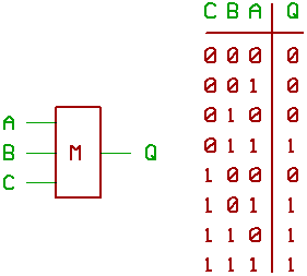
Now to describe, what to do with such a gate.
Take the table of logic states on the right,
and imagine to have a binary full adder,
with the inputs A, B, and C like "carry input".
The output of our majority gate exactly
works like the carry output of a full adder.
Interesting, isn't it ?
Remember: if at least two inputs of our three_input
majority gate are 1, the output Q is 1.
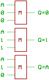
If you happen to have a signal 'A', and you want
to "force" it to 0 or 1, maybe with control signals,
it looks like this:
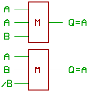
...is it possible to use this effect for
turning a majority gate into a flipflop ?
Two more cases, where Q = A:
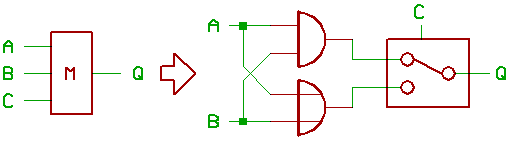
Now for another thing:
If you take a three input majority gate,
and force one of the inputs to 0 or 1,
It will turn into a two input AND gate,
or a two input OR gate.
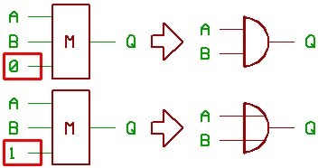
To illustrate the effect:
...this could be neat for ALU design.
Be aware, that it's possible to swap the
inputs of a majority gate. So you could as
well draw the picture above with B and C
connected to the AND/OR gates, while A
throws the switch... for instance.
[HOME] [UP]/ [BACK] [1] [2] [3] [4] [5] [6] [7] [8] [NEXT]
(c) Dieter Mueller 2009