Journal of applied sciences, ISSN1812-5654, 2007:
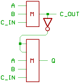
Two majority gates and one inverter.
But building this thing with the knowledge
we have by now may give you a few grey
hairs...
Problem is, that the second majority gate
has five inputs...
and maybe you would want to use a fast
comparator instead of a CMOS logic gate
to build said majority gate.
The obsolete MC14530 is a five_input majority
gate, but this IC is supposed to be extinct.
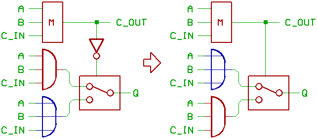
We already know, that when taking a three_input
majority gate and setting one of the
inputs to 0 or 1, it can be configurated
to work as a two_input AND, or a two_input
OR gate.
Same thing, when taking a five_input
majority gate, and wiring two inputs
together while setting them to 0 or 1.
It will be configurated as a three_input
AND or OR gate.
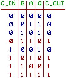
To control the functionality of our
configurable three_input AND/OR gate,
we take the output of the carry chain.
Blue entries in the table:
the five_input majority gate turns
into a three_input OR gate.
Red entries:
the five_input majority gate turns
into a three_input AND gate.
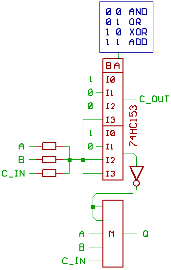
And that's exactly the problem:
the three_input AND gate.
To make use of the AND functionality
of a hypothetical ALU, we would have to
force the outputs of the carry chain to 1,
to make the three_input AND work.
We also would have to force it to 0
to make the three_input OR work.
And don't forget to add another multiplexer in
front of your ALU to force the carry input of
the ALU to 0 or 1...
To make things worse: if we would tie the
control input of our three_input AND/OR gate
directly to the carry chain, me have to take
care not to loose/void the XOR functionality.
Now you know, why this approach may give you
a few grey hairs, and why I won't recommend
using it.
If you now say:
Nice, let's build CMOS inverters with logic level
FETs and wire them together with resistors to have
a set of neat majority gates...
you should be aware, that in 2009, the capacitances
of logic level FETs like BSS138 are still a bit high,
and that your inverter may take 50 mA from the
power supply when running at 3 MHz...
resistors not counted.
Better try less power hungry things instead...
like building ECL based currend mode adders.
That's all for now.
On to part 5.
[HOME] [UP]/ [BACK] [1] [2] [3] [4] [5] [6] [7] [8]
(c) Dieter Mueller 2009