The most commonly used JK flipflops were the
7473 and the 7476.
Before you start experimenting, I would suggest
that you take a close look at the datasheet,
to check if the flipflop you are using is
triggered at the rising or the falling edge
of the clock signal.
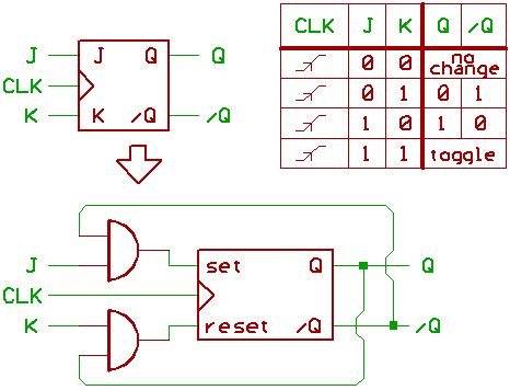
For this article, we assume that the flipflop
is triggered at the rising edge of the clock signal.
"Toggle" means that Q turns from 0 to 1...
or from 1 to 0.
Now you know, how to build a one_Bit counter.
Loading a Bit from the data bus is simple:
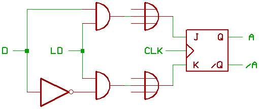
If the enable signal LD is 1, the data is stored
at the rising edge of CLK.
If LD=0, the J and K inputs of the flipflop are 0,
and the data inside the flipflop won't change at
the rising edge of CLK.
The open inputs at the OR gates are there to remind
you that there might be some other AND gates
(not shown in this schematic) which feed the JK
inputs, since we want to build an ALU on the next
page of this article.
Transfering data from one JK flipflop to another:
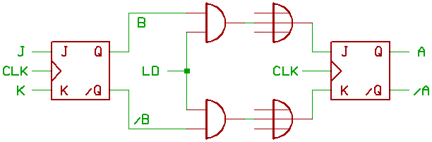
You sure can imagine now, how to build a shift register.
One Bit bitslice of a shift register (Bit 1).
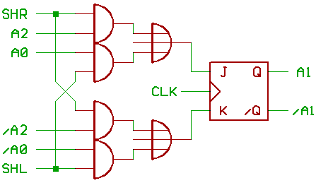
SHL=1 shifts left,
SHR=1 shifts right.
Note: for arithmetic shift right, you may want to
surpress the SHR control signal for the uppermost
Bit of the shift register.
[HOME] [UP]/ [BACK] [1] [2] [3] [4] [5] [6] [7] [8] [NEXT]
(c) Dieter Mueller 2012