Now to describe the architecture of the flipflops used in MT15.
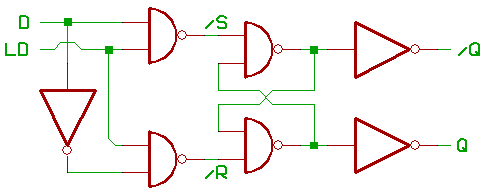
First, a simple, transparent latch with buffered outputs.
The "traditional" approach, as known from school books:
Looks like we could eliminate the inverter at the input:
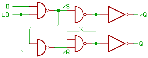
Since we are using open_collector NANDs, it's
possible to replace one NAND with an inverter:
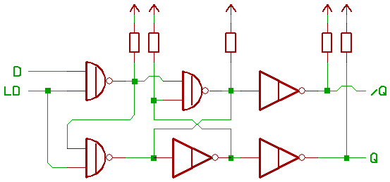
This sort of flipflop is used in the instruction_latch,
the flags, and the sequencer.
Now to describe the flipflops, used in the one_Bit register_slices:
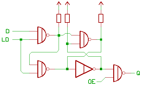
Main difference to our previous flipflop schematic:
An open_collector NAND with output_enable, connecting to a bus.
(bus pullup_resistor not shown).
Note that T0,T1 have multiple outputs with different output_enables.
[HOME] [UP]/ [BACK] [1] [2] [3] [4] [5] [6] [7] [8] [NEXT]
(c) Dieter Mueller 2005