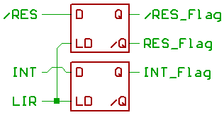
Now for the Flag circuitry.
Since Reset and external "Interrupt" have a noticable effect
on OpCode execution,
those signals are sampled when loading the
OpCode into the instruction register.
Reset signal is low_active, please notice the polarity at the outputs of the Reset_flipflop.
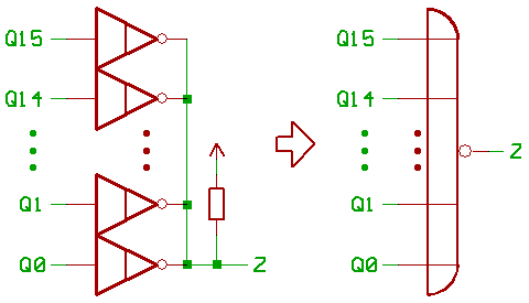
Each one_Bit ALU slice contains an open_collector inverter.
Input is connected to ALU Q.
Outputs of those 16 inverters are wired together, so that they
work as a 16_input NOR gate, testing the ALU output for Zero.
Negative ALU result is determined by ALU Q15.
We already discussed the carry signals.
NOTE: ALU output carry !C16 is low_active.
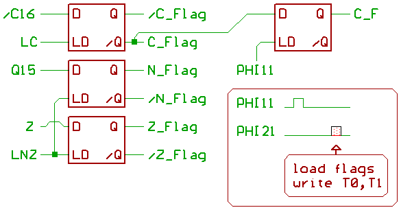
N,Z could be fetched with transparent latches.
Since we need to route the carry flag from the previous
data calclation into the ALU,
carry requires two
transparent latches wired up in a master/slave configuration.
Now for part two:
The MT15 instruction decoder/sequencer.
[HOME] [UP]/ [BACK] [1] [2] [3] [4] [5] [6] [7] [8]
(c) Dieter Mueller 2005