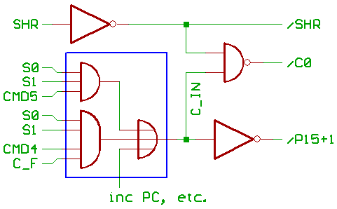
Carry_input multiplexer:
Data calculation happens in sequencer_step number three.
Since the sequencer counts from 0 to 5, I decided to check
only Bit 0,1 from the sequencer to identify a data calculation.
Opcode Bit 4 = 1 routes the Carry flag to the ALU carry input,
Bit 5 = 1 forces the ALU carry input to 1.
Since the ALU increments when C0 is active, it became
necessary to disable that signal when shifting right.
Note: the blue marked gates use complementary transistor logic,
and are part of the "programmable" logic array.
Data calculation happens in step 3, but ALU carry_input could
also be forced active in other steps.
Like for incrementing PC (Program Counter).
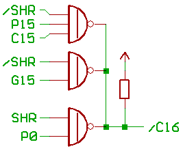
Carry_output multiplexer:
For shifting right, we take the ALU propagate signal from Bit 0
as a carry output.
Since I had inverted/non_inverted propagate and generate signals,
I decided to use ALU Bit 15 propagate/generate/carry to produce
the carry output for all other ALU_operations.
[HOME] [UP]/ [BACK] [1] [2] [3] [4] [5] [6] [7] [8] [NEXT]
(c) Dieter Mueller 2005