3.2. Optimisation of Compression/Expansion
As presented in Section 3.1.1: , the technical work can be represented by the aera on the left of the curve corresponding to the reversible transformation in the Clapeyron diagramm.
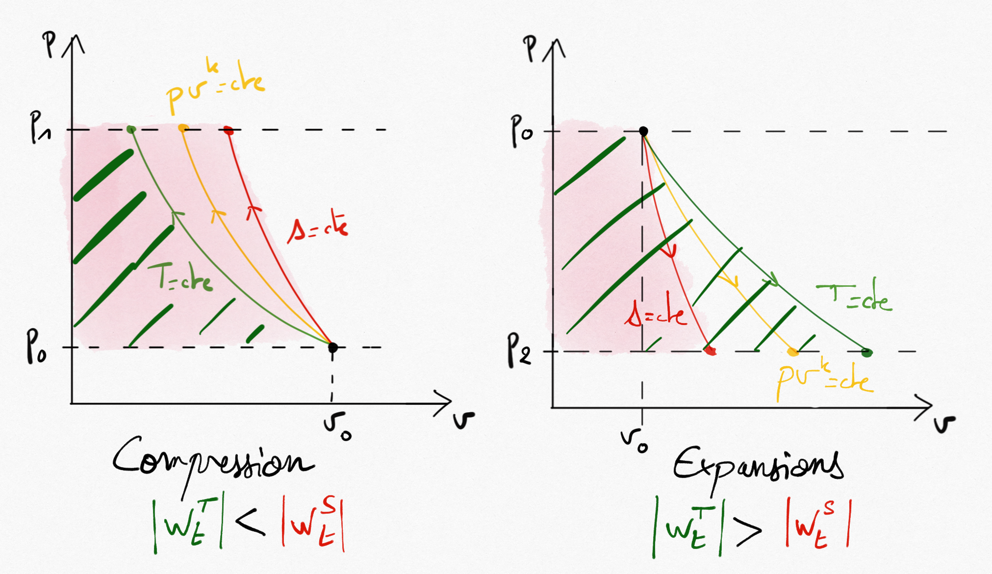
Figure 3.5: For a compression, the required technical work is minimum for the isothermal transformation. For an expansion, the provided technical work is maximum for the isothermal transformation.
The lower mechanical work needed for a compressor is the better and the bigger is the mechanical work supplied by a turbine is the better.
Important
As shown on Figure 3.5: , it is clear that:
For a compressor, optimisation will be obtain by cooling
For a turbine, optimisation will be obtain by heating
3.2.1. Compression optimisation
The minimum technical work for a compressor corresponds to isothermal transformation. There are two techniques to approach isothermal transformation in a compressor:
Continuous cooling of the compressor
Multi-stage compressions with intercooling
3.2.1.1. Continuous cooling
Continuous cooling can be performed with surrounding the compressor with a cooling pipe. It is possible to quantify the cooling interest of a compression by comparison between the technical work needed for an isentropic and those obtained for an isothermal transformation. We define the theoretical cooling efficiency:
(3.17)
Under ideal gas assumption, using relations Eq.3.8 and Eq.3.6, it becomes:
(3.18)
Where  represent the compression pressure ratio.
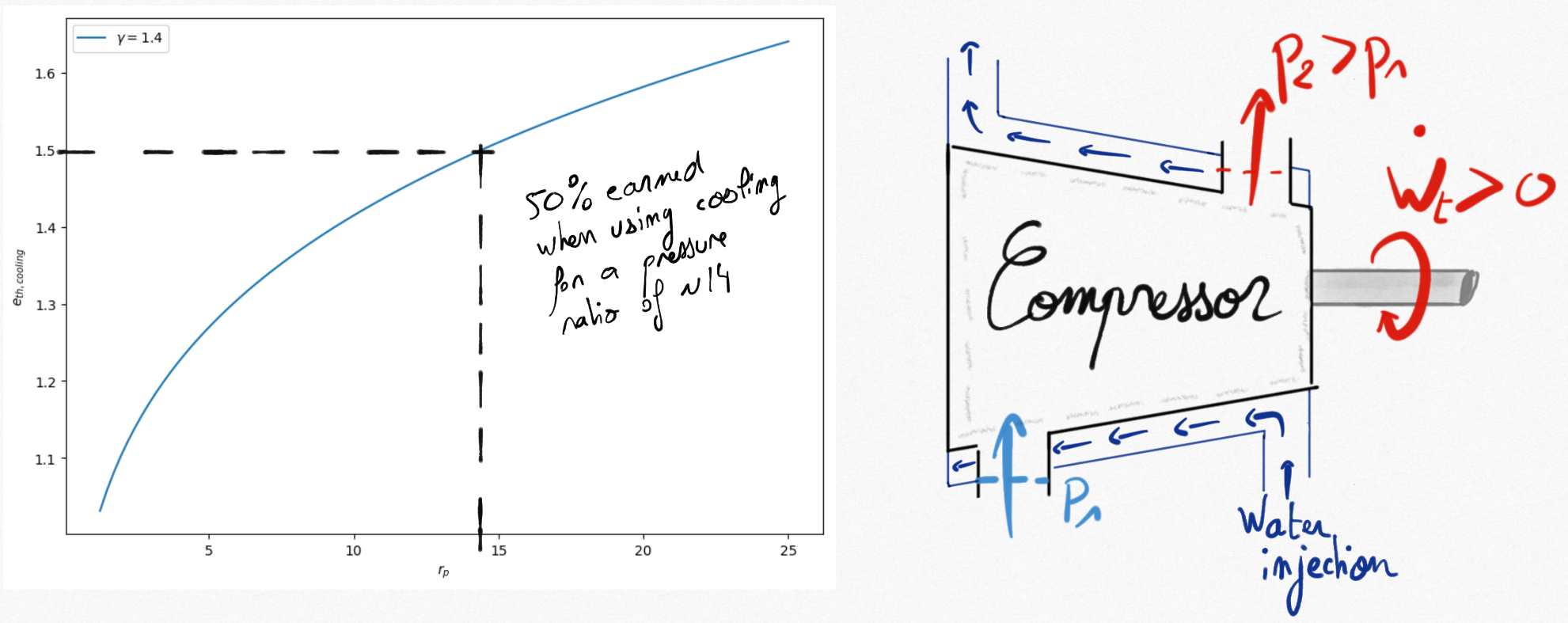
Figure 3.6: For a pressure ratio of 14, the mechanical energy earned for an isothermal compression is 50% compared to an isentropic one.
Efficiency of cooling is theroretical since it is difficult to ensure an isothermal compression using continuous cooling and heat transfer through the compressor carter.
3.2.1.2. Multi-stage cooling
Multi-stage cooling is often used for multi-stage compression. It consists in cooling the fluid using a heat exchanger between two compression stages.
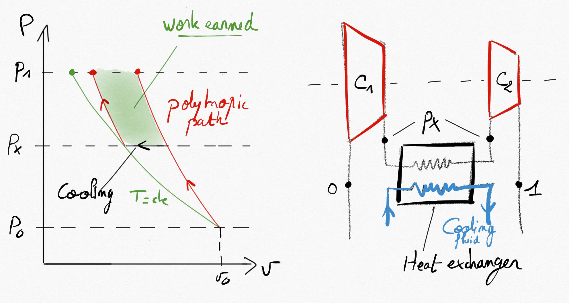
Figure 3.7: Two-stage compression. Transformations in compressors are polytropic (adiabatic or not) and a constant pressure heat exchange occurs between the two stages of compression. The earned work is clearly visible on the Clapeyron diagramm.
How to choose the compression ratio of each stage ?
The technical work for the global two-stage compression is:

If the two compression stages perform a polytropic compression, thanks to Eq.3.10 we get:
![w_{t} = \frac{krT_0}{k-1} \left[ \left( \frac{p_X}{p_0} \right)^{\frac{k-1}{k}} -1 \right] + \frac{krT_0}{k-1} \left[ \left( \frac{p_1}{p_X} \right)^{\frac{k-1}{k}} -1 \right]](_images/math/b045c42f982e632cab45437d3c80b5bad480cfad.svg)
Derivation of this expression using  variable leads to:
![\frac{d w_{t}}{d p_X} = \frac{krT_0}{k-1} p_X^{\frac{1}{k-1}} \left[ p_0^{\frac{-k}{k-1}} - p_1^{\frac{k}{k-1}} p_X^{\frac{-2k}{k-1}} \right]](_images/math/2782690b96f434df655640914da5b72964b7f6e8.svg)
such that the technical work is minimum for:

This result can be extand to multi-stages compressions.
Important
The pressure ratio in each stage of a multi-stage compression with intercooling should be equal in order to minimize the technical work.
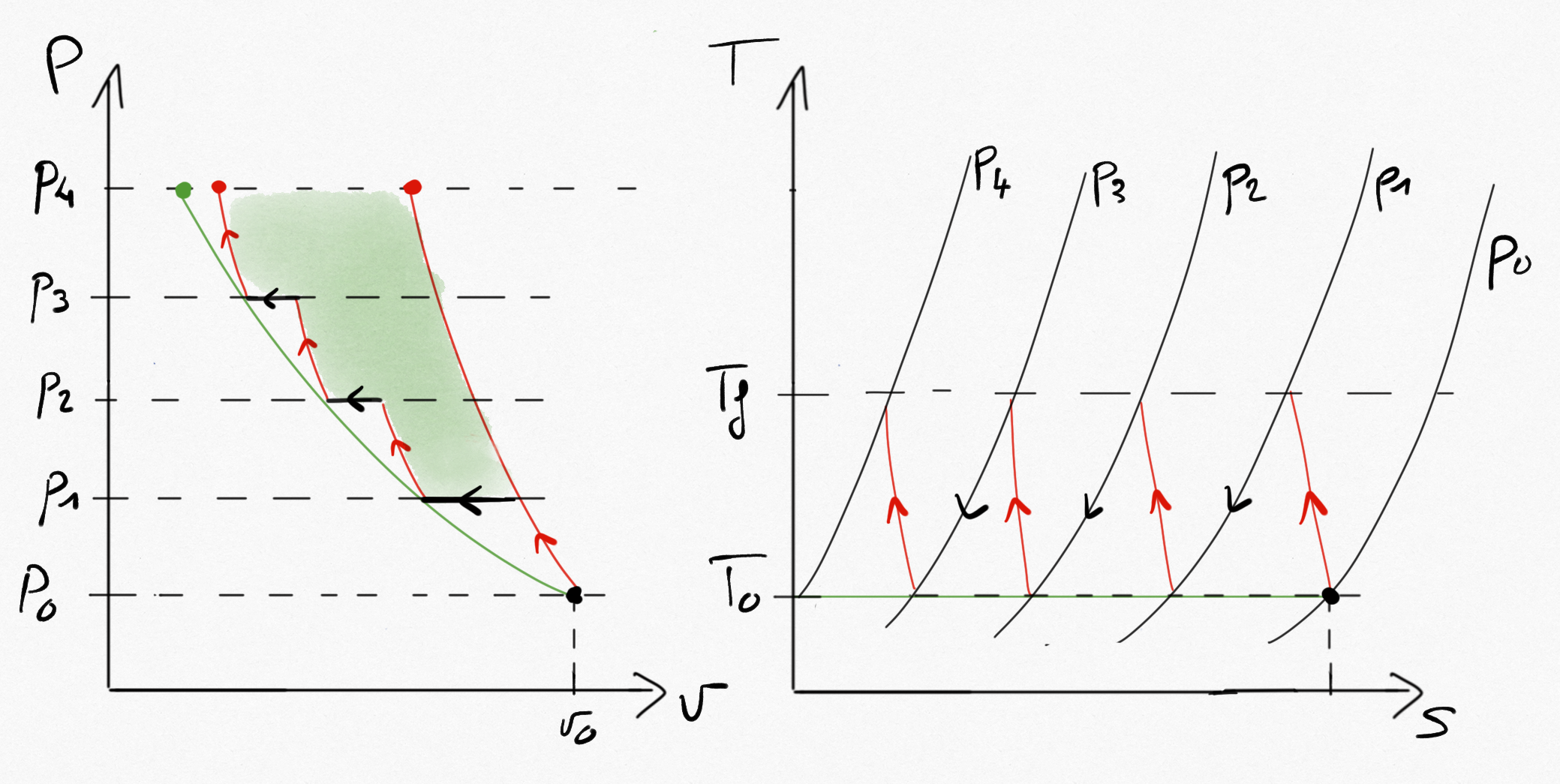
Figure 3.8: Multi-stage compression with intercooling.
3.2.2. Turbine optimisation
The maximum technical work for a turbine correspond to isothermal transformation. This is generally obtain by multi-stage expansions with reheat.
Conclusions are similar than those obtain with multi-stage compression with intercooling and are not developped here.