Examples > Control Structures
While Loop
A while loop is a section of code that will loop as long as the conditional argument is true. While loops are popularly used as forever loops using while(1) or while always true, so that code loops during the entire program execution, theoretically forever.
Hardware Required
- MSP430 LaunchPad
- (1) digital pushbutton or switch
- (1) photocell, or analog sensor
- (2) 10k ohm resistors
- breadboard
Relevant Groundwork
Sometimes you want everything in the program to stop while a given condition is true. You can do this using a while loop. This example shows how to use a while loop to calibrate the value of an analog sensor.
In the main loop, the sketch below reads the value of a photoresistor on analog pin A3 and uses it to fade an LED on pin 14. But while a button attached to digital pin 6 is pressed, the program runs a method called calibrate() that looks for the highest and lowest values of the analog sensor. When you release the button, the sketch continues with the main loop.
This technique lets you update the maximum and minimum values for the photoresistor when the lighting conditions change.
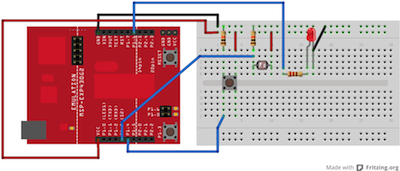
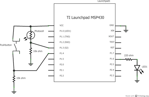
Connect your analog sensor (e.g. potentiometer, light sensor) on analog input A3 with a 10K ohm resistor to ground. Connect your button to digital pin 6, again with a 10K ohm resistor to ground. Connect your LED to digital pin 14, with a 220 ohm resistor in series.
Circuit

image developed using Fritzing. For more circuit examples, see the Fritzing project page
Schematic:

Code Explanation
None.
Code
/*
  Conditionals - while statement

  This example demonstrates the use of  while() statements.

  While the pushbutton is pressed, the sketch runs the calibration routine.
  The  sensor readings during the while loop define the minimum and maximum
  of expected values from the photo resistor.

  This is a variation on the calibrate example.

  The circuit:
  * photo resistor connected from +3V to analog in pin A3
  * 10K resistor connected from ground to analog in pin A3
  * LED connected from digital pin 14 to ground through 220 ohm resistor
  * pushbutton attached from pin 6 to +3V
  * 10K resistor attached from pin 6 to ground

  created 17 Jan 2009
  by Tom Igoe
  modified 30 Apr 2013
  by Adrian Fernandez

  This example code is in the public domain.

*/


// These constants won't change:
const int sensorPin = A3;       // pin that the sensor is attached to
const int ledPin = 14;           // pin that the LED is attached to
const int indicatorLedPin = 2; // pin that the built-in LED is attached to
const int buttonPin = 6;        // pin that the button is attached to


// These variables will change:
int sensorMin = 1023;  // minimum sensor value
int sensorMax = 0;     // maximum sensor value
int sensorValue = 0;         // the sensor value


void setup() {
  // set the LED pins as outputs and the switch pin as input:
  pinMode(indicatorLedPin, OUTPUT);
  pinMode (ledPin, OUTPUT);
  pinMode (buttonPin, INPUT);
}

void loop() {
  // while the button is pressed, take calibration readings:
  while (digitalRead(buttonPin) == HIGH) {
    calibrate();
  }
  // signal the end of the calibration period
  digitalWrite(indicatorLedPin, LOW);

  // read the sensor:
  sensorValue = analogRead(sensorPin);

  // apply the calibration to the sensor reading
  sensorValue = map(sensorValue, sensorMin, sensorMax, 0, 255);

  // in case the sensor value is outside the range seen during calibration
  sensorValue = constrain(sensorValue, 0, 255);

  // fade the LED using the calibrated value:
  analogWrite(ledPin, sensorValue);
}

void calibrate() {
  // turn on the indicator LED to indicate that calibration is happening:
  digitalWrite(indicatorLedPin, HIGH);
  // read the sensor:
  sensorValue = analogRead(sensorPin);

  // record the maximum sensor value
  if (sensorValue > sensorMax) {
    sensorMax = sensorValue;
  }

  // record the minimum sensor value
  if (sensorValue < sensorMin) {
    sensorMin = sensorValue;
  }
}
Working Video
(Insert Video Here)Try it out:
- run a while loop and then try and exit it cleanly by changing the value of the conditional inside the codeSee Also:
- while()
- digitalRead()
- digitalWrite()
- analogRead()
- analogWrite()
- map()
- constrain()
- if()
- For Loop - Control multiple LEDs with a For Loop.
- Switch Case - Choose between a number of discrete values in a manner that is the equivalent of using multiples If statements. This example shows how to divide a sensor's range into a set of four bands and to take four different actions depending on which band the result is in.
- Array: a variation on the For Loop example that demonstrates how to use an array.
Corrections, suggestions, and new documentation should be posted to the Forum.
The text of the Energia reference is licensed under a Creative Commons Attribution-ShareAlike 3.0 License. Energia reference is based on the Arduino reference. Code samples in the reference are released into the public domain.