Central to the concept of what Rhapsody does is the route, or the path taken by a message as it passes through the Rhapsody engine. This path connects input communication points to output communication points and may include intermediary filters designed to complete a variety of tasks, such as conditionally passing the message or transforming the message from one format to another.
The following example illustrates how to build and test a simple pass-through route:
Refer to Route Design Considerations for best practices when building routes.
Example of Pass-through Route
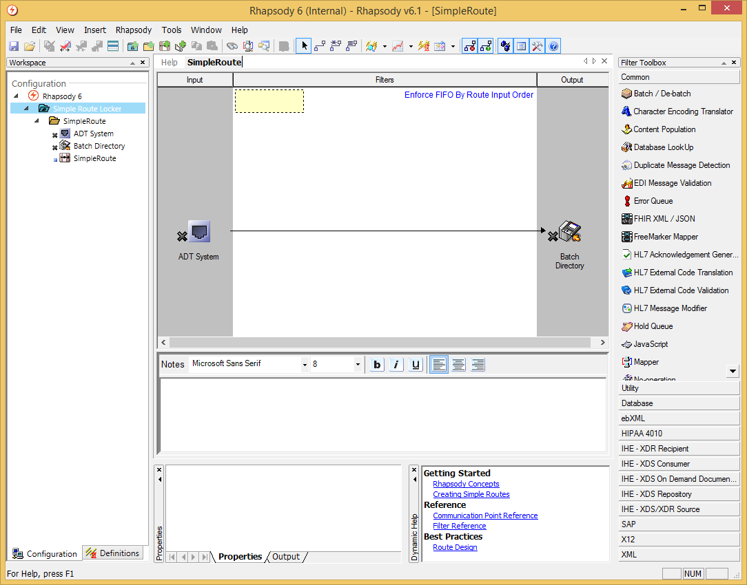
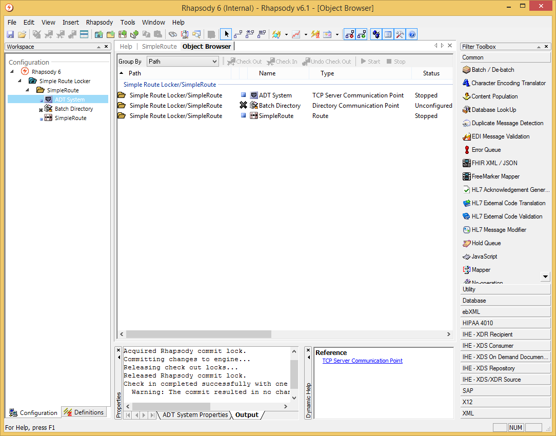
In this example pass-through route, messages arrive at a TCP Server communication point called "ADT System" and are passed to the Directory communication point called "Batch Directory":
The route utilizes the following Rhapsody applications and components:
- EDI Explorer - used to generate test messages and connect with the ADT System communication point. Test messages are then sent from EDI Explorer into the route.
The communication points included in this route are: - ADT System - an input TCP Server communication point configured to receive messages from an external application.
- Batch Directory - an output Directory communication point configured to save received messages to a specified network location.
Create the Route
To create a route:
- Create a locker if required.
- Create a folder if required.
- Define the communication points.
- Define the route.
- Add filters.
- Check in the components.
Define the Communication Points
The next step is to create the communication points. Communication points are entry or exit points to the Rhapsody engine. Communication points are the interface to the external system and are the mechanism by which Rhapsody sends and receives information to and from the external systems. Messages arrive at an Input communication point, are processed by the filters and conditional connectors in the route and passed to one or more Output communication points. From there, the messages are sent to the receiving applications.
To create a communication point:
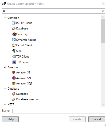
Select the New Communication Point iconon the standard toolbar. The Create Communication Point dialog is displayed:
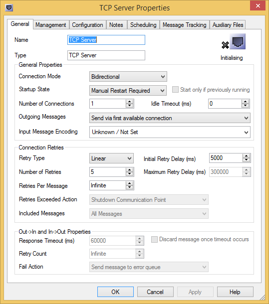
Select TCP Server, and select the Create button. The TCP Server Properties dialog is displayed:
- Enter the following details:
- Name -
ADT System. A communication point's name is not case-sensitive and must differ from all other communication points in the same folder. An alert is displayed if this is not the case. - Type -
TCP Server. The TCP Server communication point listens for connections on the port specified as part of its configuration. - Template -
None. - Connection Mode-
Input. Input communication points are configured to receive messages from one or more external systems.
- Name -
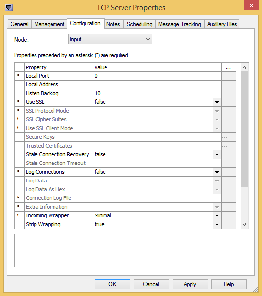
Select the Configuration tab to display the Configuration dialog and define the following properties:
Local Port -
3001. The port can be changed if there is a conflict.
- Select the OK button to save your changes.
- Repeat Steps 1 through 5 to create a Directory communication point with the following properties:
- General tab:
- Name-
Batch Directory. - Type-
Directory. - Connection Mode-
Output. Output communication points are configured to send messages to one or more external systems.
- Name-
- Configuration tab:
- Output Directory - the location where files will be sent.
- General tab:
For details on how to:
- Manage communication points, refer to xxx.
- Configure individual communication point types, refer to Communication Point Types.
Define the Route
The next step after creating the communication points – one for receiving and one for sending messages – is to create a route to link the communication points.
To create a new route:
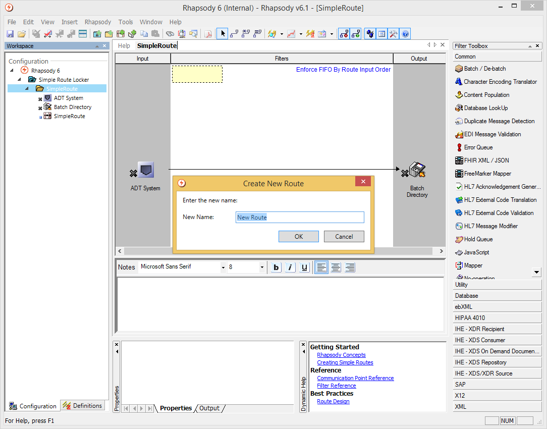
Select the New Route icon on the standard toolbar. Enter a name for the route and the new route is created in the Route Editor, as shown in the following screenshot. It has an Input section, a Filters section, and an Output section. The Input section is where the Input communication points belong and the Output section is where the Output communication points belong.
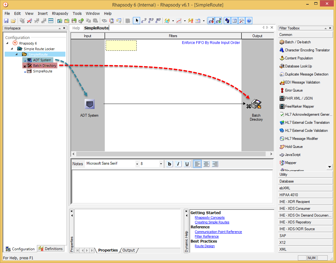
Drag and drop your Input and Output communication points to the appropriate sections in the Route Editor:
- Connect the input communication point to the output communication point.
- Select the Connector icon on the standard toolbar.
- Select the Input communication point and drag a line to the Output communication point.
For details on how to configure routes, refer to Routes.
Add Filters
While this example route does not include filters, you can add a filter by dragging it from the Filter Toolbox onto the Filters section in the Route Editor.
For details on how to:
- Manage filters, refer to Managing Filters.
- Configure individual filter types, refer to Filter Types.
Check In the Components
The next step is to check in your communication points and routes so the engine is aware of your changes.
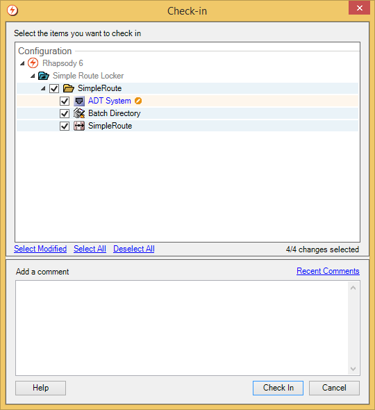
Select the Check in all routes and communication points icon on the standard toolbar. The Check-in dialog is displayed:
Select the components you want to check in, and select the Check In button. Rhapsody checks the configuration of each component when it is checked in.
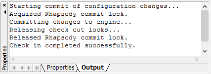
If any errors are found they are listed in the Properties pane at the bottom of the Rhapsody IDE window:
- If required, save your configuration.
For details on:
- Version control in Rhapsody, refer to Modifying a Configuration.
- Saving your current configuration, refer to Saving a Configuration.
Starting and Stopping Components
When a route or communication point is first created, its Status is Stopped by default, unless its configuration is incomplete. Rhapsody checks the configuration of a component when it is checked in. If any errors are found they are listed in the Properties pane.
Routes and communication points must be started before they can process messages. Messages sent to a stopped route or communication point will be queued by Rhapsody until the component is restarted, at which time the backlog is cleared before new messages are processed.
You can start or stop a component in one of the following ways:
Workspace
Right-click the component, and select Start or Stop.
Object Browser
- Right-click the component, and select Start or Stop.
Select the component, and the Start or Stop icons on the Object Browser toolbar.
Management Console
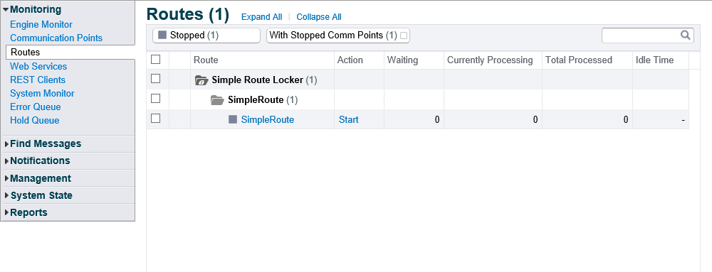
Launch the Management Console and navigate to Monitoring>Communication Points or Monitoring>Routes.
To change the status, in the Action column, click the Start or Stop link.
The following icons are used in Rhapsody IDE (Workspace and Object Browser) to identify the component's current status:
Icon
Description
The component has started.
The component is stopped.
One or more required properties are missing, therefore, the component cannot be started or stopped.
Testing the Route
The final step is to test the route. EDI Explorer is used to create test messages and send them into Rhapsody via a TCP connection.
- Select the EDI Explorer iconon the standard toolbar.
Load a message definition, then create a new message. Refer to EDI Explorer in the EDI Explorer Reference Manual to learn how to load a message definition and create a test message, and configure the application to communicate with the ADT System communication point in Rhapsody.
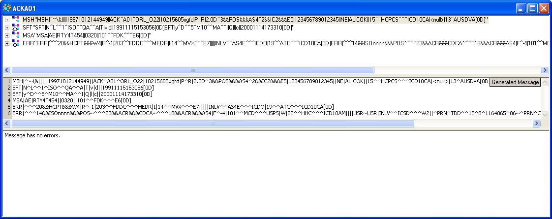
An example message has been created from the
HL7v2.3_ACKA01.s3dmessage definition and auto-filled with dummy data:- Connect to the TCP Server communication point created earlier, then select the Transmit button to send the message to the route.
- If the route is successfully processing messages, the file is processed and passed to the directory specified by the "Batch Directory" communication point.
You can also use the Management Console to track the event path of a particular message. Refer to the Management Console's Message View for details.
