4.3 Blink An LED
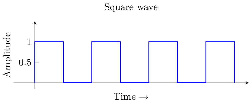
Let’s use the computer to send a binary signal out of one of its GPIO pins. Here we can see we instruct GPIO pin number 4 to turn on, then wait one second, then turn off, wait one second in the off position, then the code repeats forever…
The electric signal would look like this:
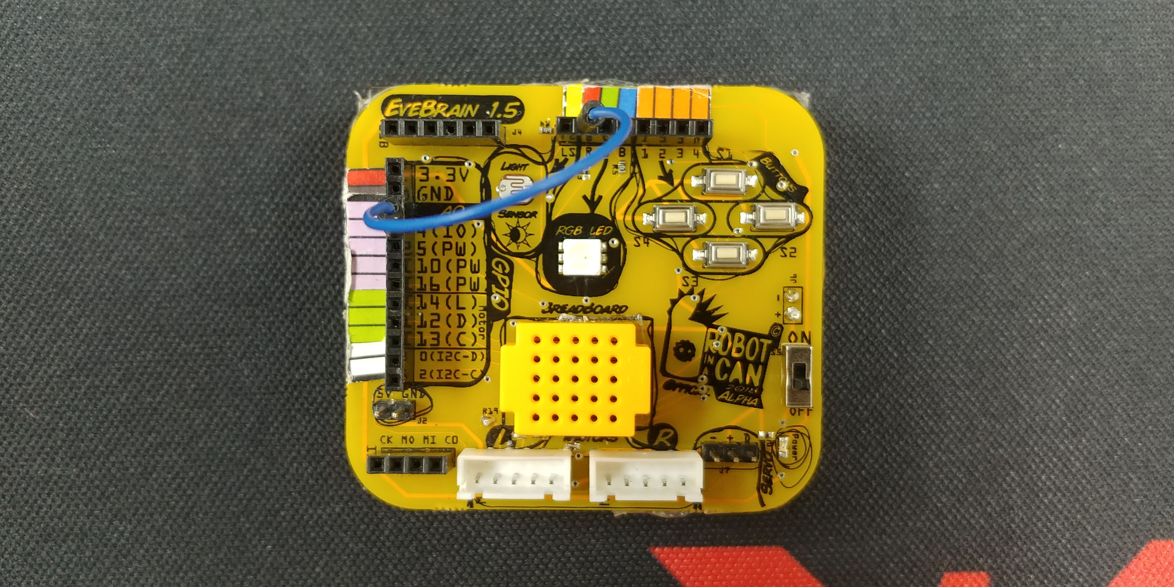
Wire Like This
GPIO # 4 <–> R
Code Screenshots
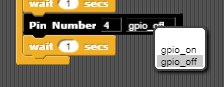
Drag to the desired GPIO pin and then choose On or Off
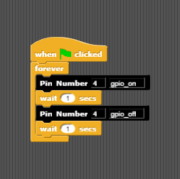
Code for LED Blink, one second on, one second off, repeat