# Details Actuator Module Assembly
## Description

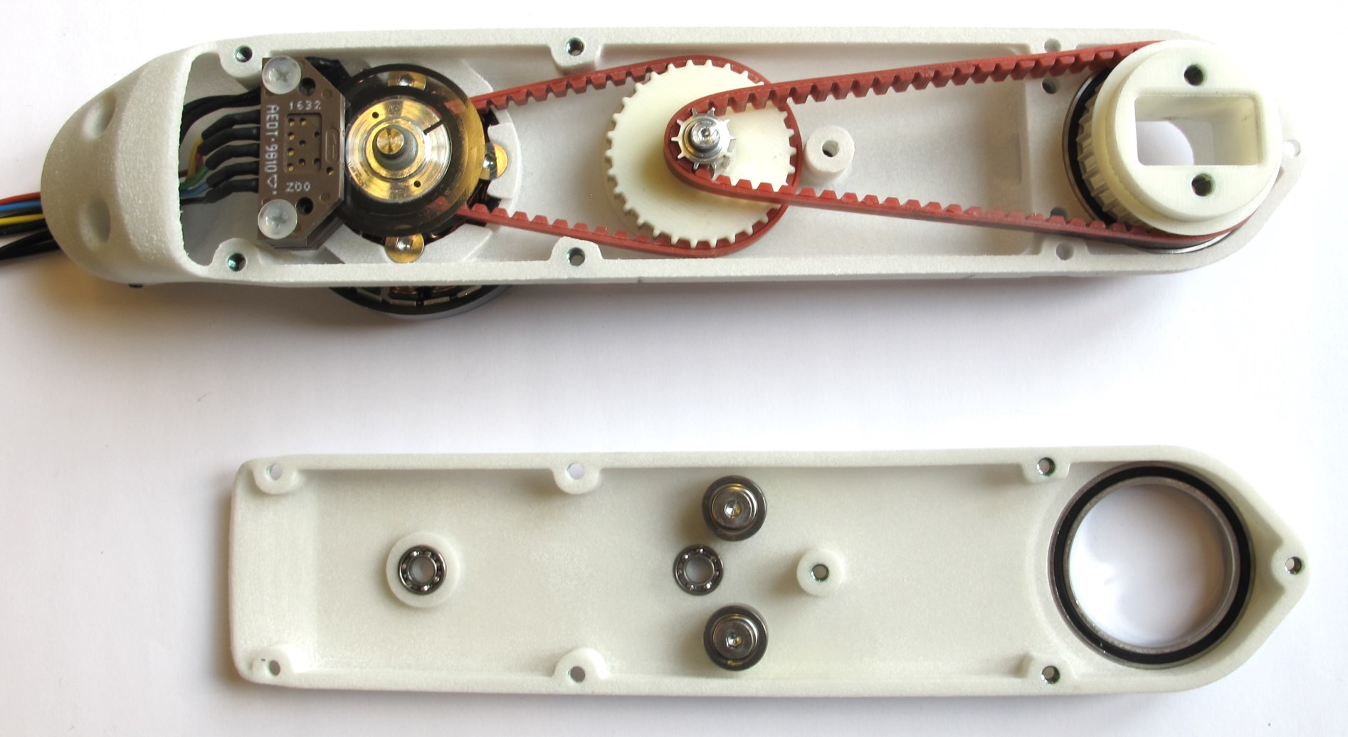
*Starting Point: The six sub-assemblies that were prepared in the previous steps.*
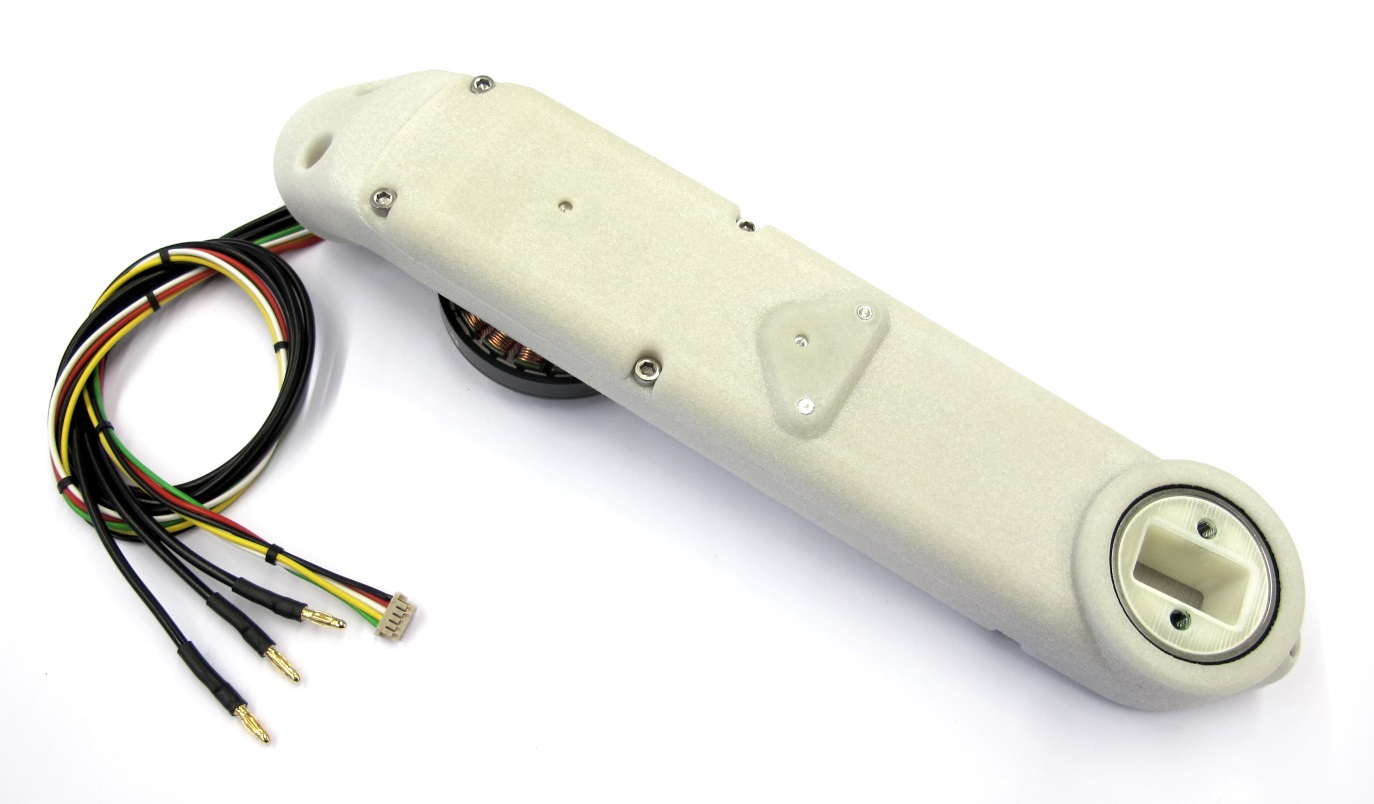
*End Result: Fully assembled actuator module.
Weight with 30cm wires: 160g*
* this page describes how to assemble the actuator modules
* the 6 sub-assemblies that were prepared before are required for this step
* instructions on how to prepare the subassemblies can be found here: [step-by-step-instructions](#step-by-step-instructions)
* in addition to the subassemblies the following components are required
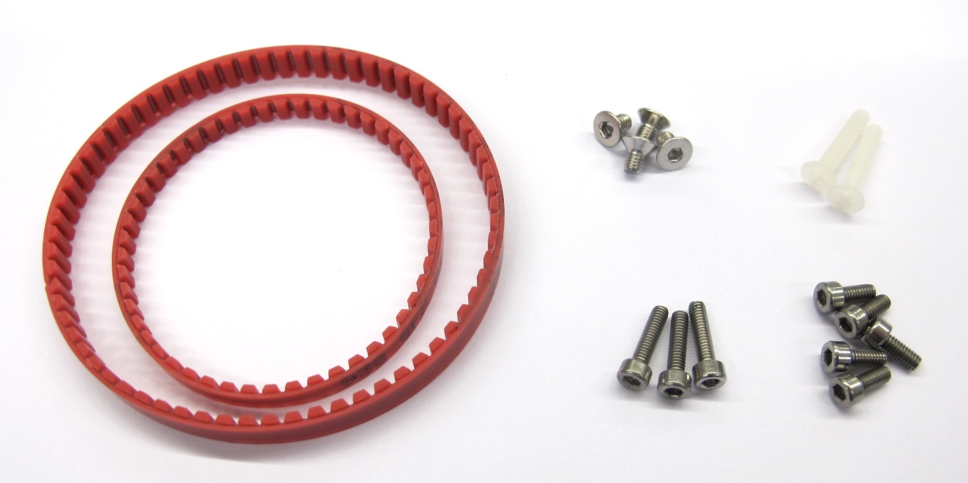
*Aditionally required components*
* 1 x Timing Belt AT3 150mm - width 4mm
* 1 x Timing Belt AT3 201mm - width 6mm
* 4 x M3x5 Flat Head Screw for motor attachment
* 2 x M3x16 Flat Head Screw for encoder attachment
* 5 x M2,5x6 Socket Head Cap Screw and
3 x M2,5x8 Socket Head Cap Screw for connecting the shells

*Fasteners for Actuator Module Assembly
FHS = Flat Head Screw*
---
### Mounting the Stator

*Route the motor phase wires through the opening in the shell.
Place the stator on the mounting surface.*
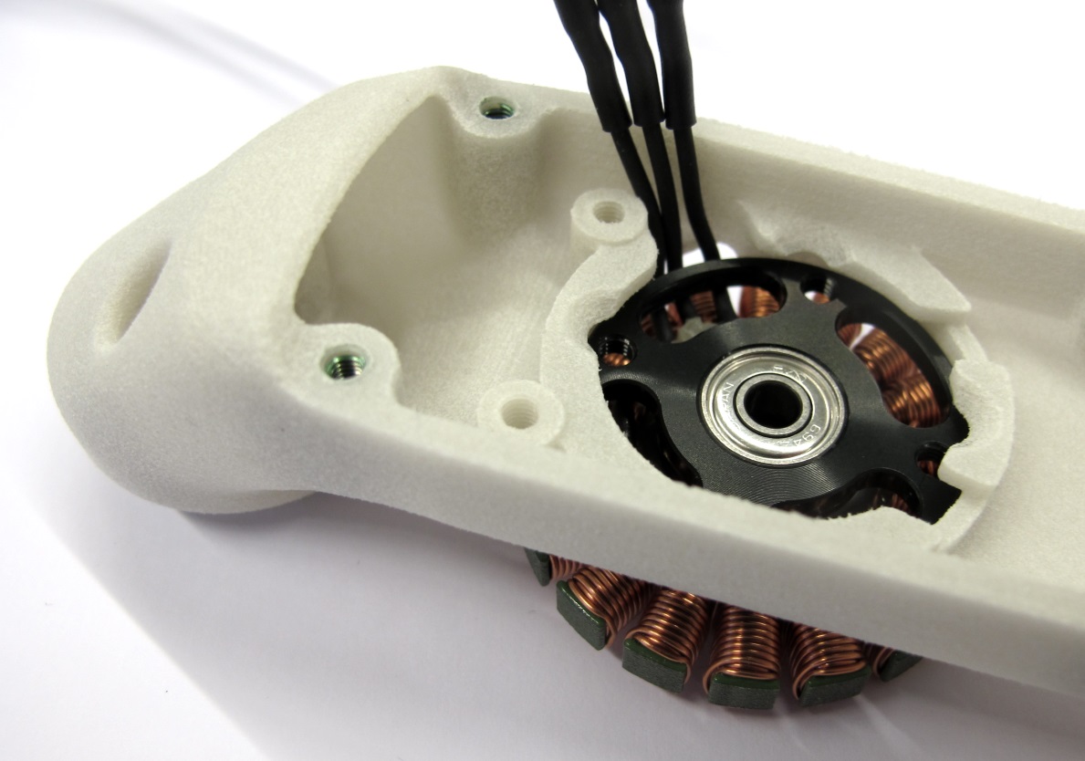
*Bend the motor phase wires up and align them with the cutout as shown in the picture.*

*Use a 2mm hex driver to install the four M3x5 flat head screws.
Make sure that the stator is fully seated and doesn't move.*
*Route the phase wires through the opening behind the encoder mount and exit through the mounting interface.*
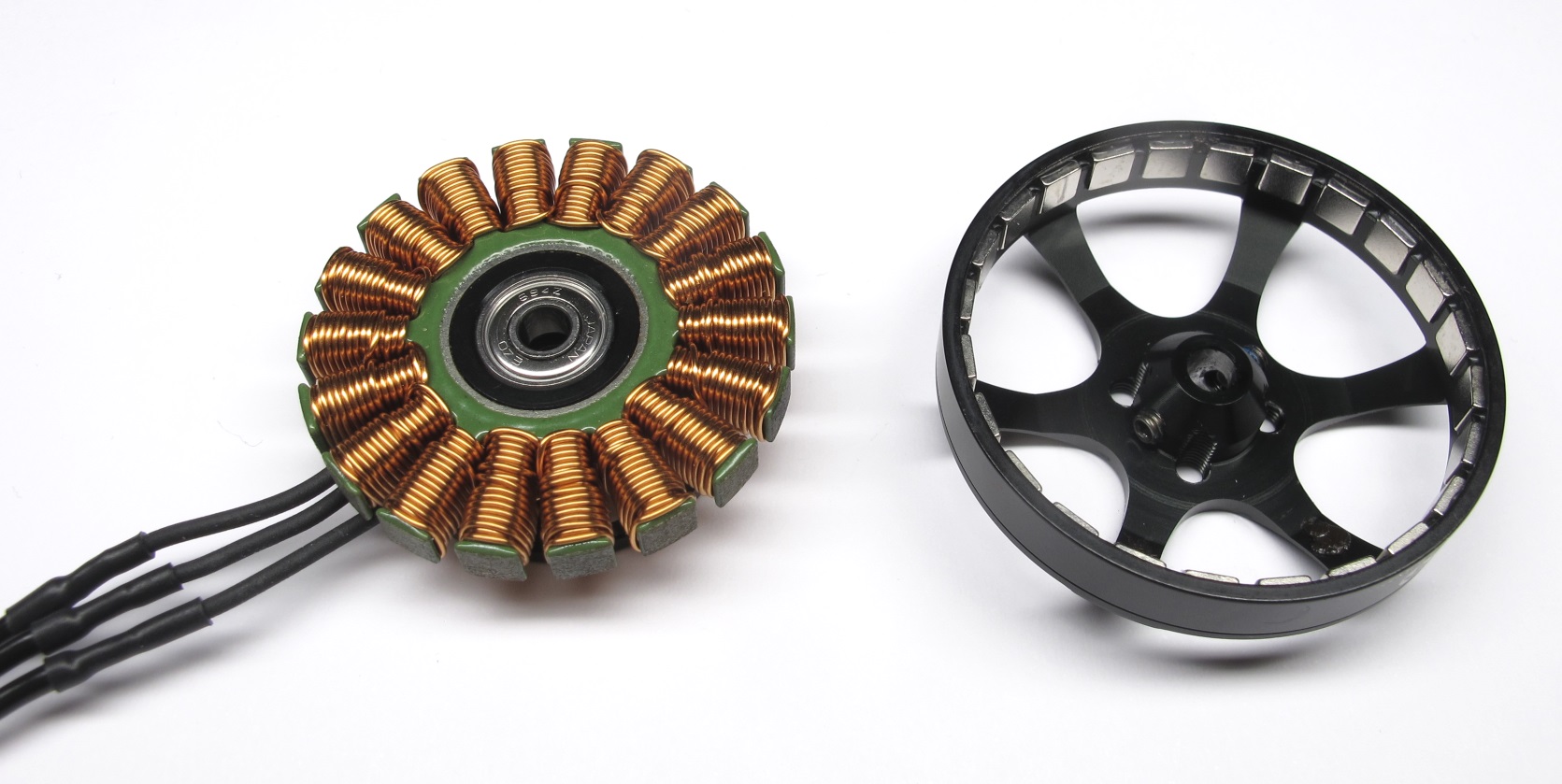
### Installing the Motor Shaft and Rotor
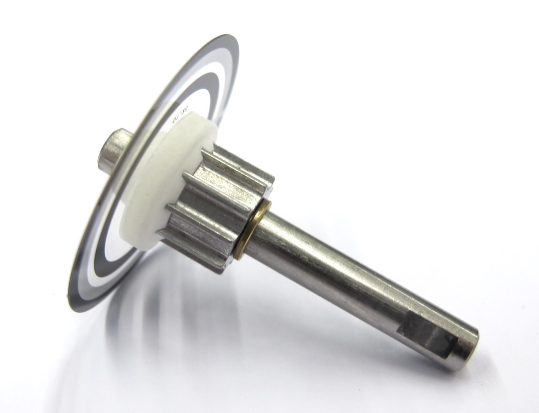
*For the next step you will need the motor shaft assembly.
Handle the codewheel with care and avoid bending or scratching it during the following steps.*
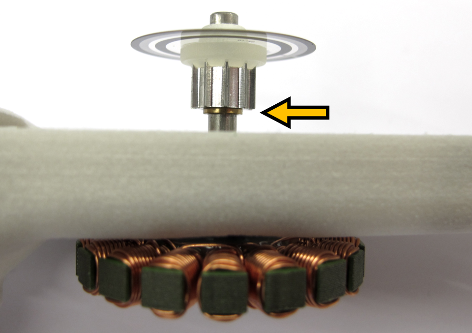
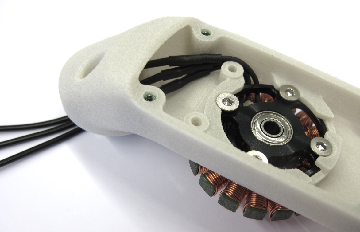
*Insert the motor shaft assembly into the stator bearing.
Make sure that the brass spacer is installed.*
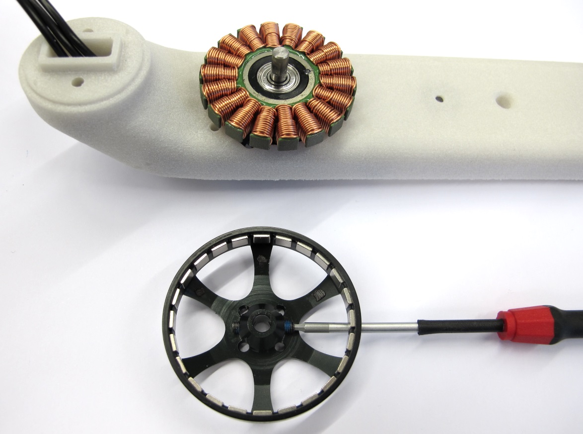
*Turn the assembly around.
Use a 1,5mm hex driver to install the two M3 setscrews half way.*

*Line up the setscrews on the rotor with the flats on the motor shaft.
Install the rotor and push it all the way down.*

*Tighten both setscrews using a 1,5mm hex driver while pushing down on the rotor.
Manually spinn the rotor to make sure that it runs freely.
Pull on the rotor in the axial direction - there should be no or only minimal play.*
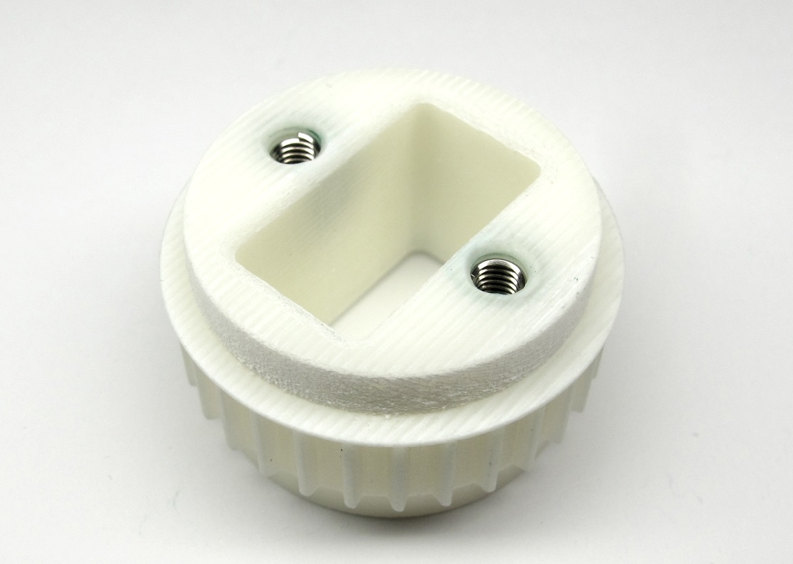
### Installing the Timing Belt Transmission

*Place the 150mm timing belt on the center pulley and engage the teeth.*

*Place the timing belt on the motor pulley and engage the teeth.*
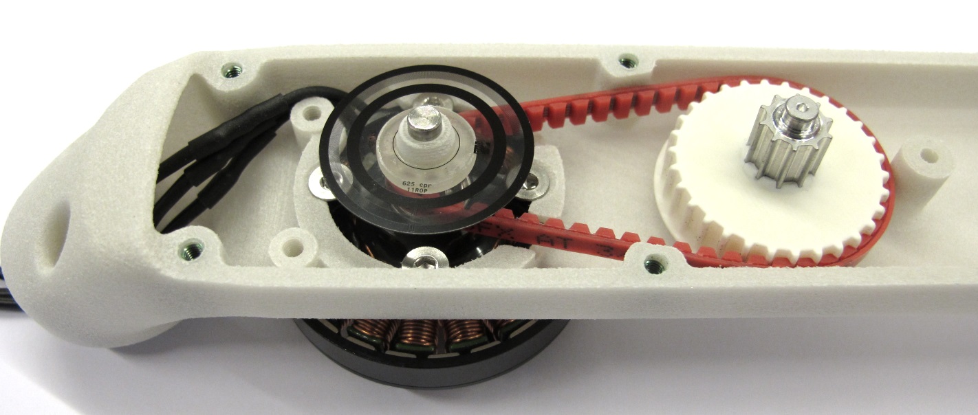
*Keep the timing belt under tension and insert the center pulley into the bearing.*

*Place the 201mm timing belt on the output pulley and engage the teeth.
Make sure that the side with the flange is facing upwards.*

*Place the timing belt on the center pulley and engage the teeth.
Keep the timing belt under tension and insert the output pulley into the bearing.*

*The timing belt transmission is now completed.
Rotate the output shaft back and forth and check if the transmission moves as expected.*
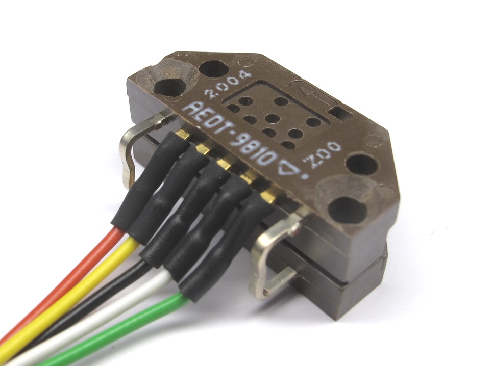
### Installing the Encoder

*For this step you will need the encoder.
Route the encoder wires through the opening in the interface.*
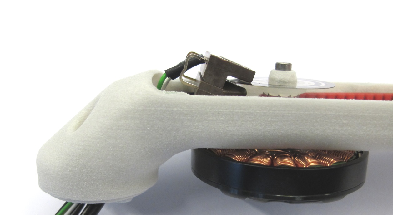
*Carefully insert the encoder under an angle such that the codewheel is located in the gap.
We shorten and bend the encoder pins to simplify the assembly.*
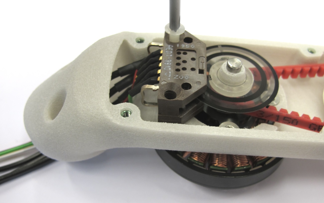
*Place the encoder on the mounting surface and install the two M3x16 screws.*

*Make sure that the codewheel is located correctly and doesn't touch the encoder.*

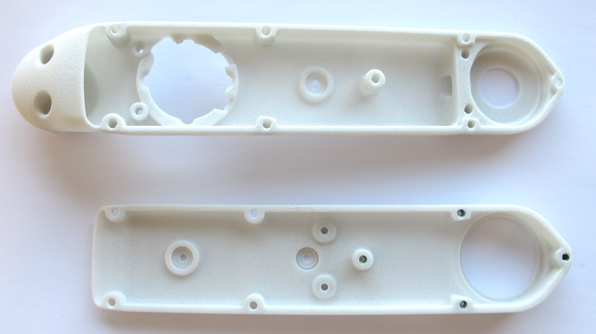
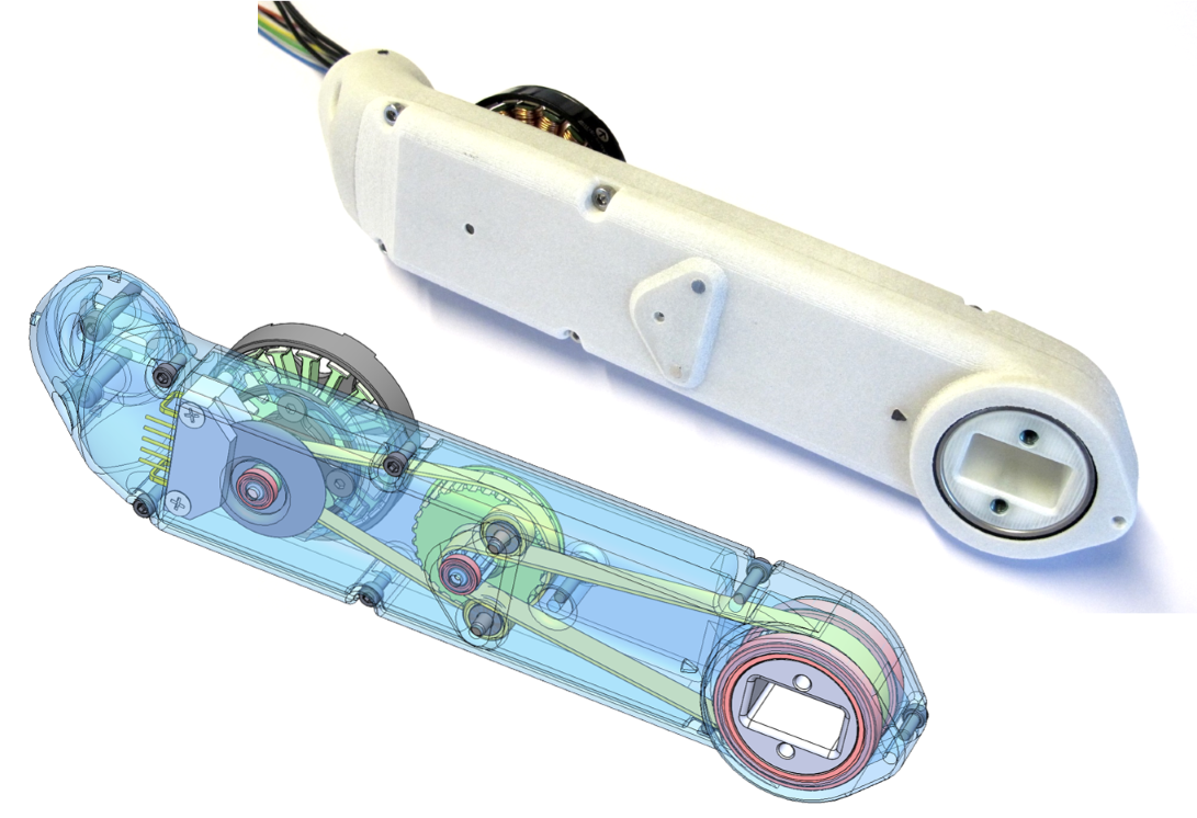
*The base of the actuator module is now completed.*
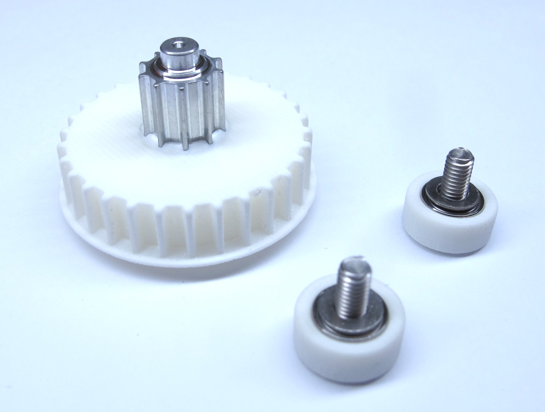
### Installing the Timing Belt Tensioner Rollers

*For this step you will need the shell cover and the timing belt tensioner rollers.*

*Make sure that the washers are installed.*

*Install the timing belt tensioner rollers using a 2mm hex driver.
Rotate the rollers and make sure that they move freely.*

*All the components are installed - the shell can now be closed.*
### Closing the Shell

*Place the shell cover on the shell base.
Angle the cover a bit and partially install the output pulley as shown above.*

*Apply moderate pressure to the center of the assembly for all the following steps.*

*You will now need to push the timing belt of the second stage inwards.
That helps the timing belt to clear the tensioner rollers.*

*Use a small flat head screw driver to push the timing belt inwards.
Keep applying moderate pressure while turning the assembly around.*

*Use a small flat head screw driver to push the timing belt inwards on the opposite side.
The cover should move downwards a bit when the timing belt clears the roller.*

*Now the center pulley needs to find its way into the bearing on the cover.
Grab the rotor and rotate it back and forth a couple of times while gently pushing down on the cover.*

*The cover should close after a couple of turns in each direction.
Make sure that the shell is fully closed and that the motor can be rotated.*

*If you have trouble closing the shell you can use a pointed tool to guide the center pulley into the bearing.
There is a hole in the center pulley for that purpose.*

*Use a pointed tool to push the center pully into the direction of the motor.
Turning the rotor at the same time can help.*

*When the shell is fully closed the fasteners can be installed.*

*Use a 2mm hex driver to install the eight connecting screws.
Tighten the screws with moderate torque.
The location of the screws is documented below.*

*Fasteners for connecting the Actuator Module Assembly
SHCS = Socket Head Cap Screw*

*The actuator module is now fully assembled.
The last step is to add the motor phase and encoder connectors.*
### Soldering the Motor Phase Connectors

*[Instructions Soldering the Motor Phase Connectors](details_motor_preparation.md#soldering-the-motor-phase-connectors)*
### Crimping the Encoder Connector
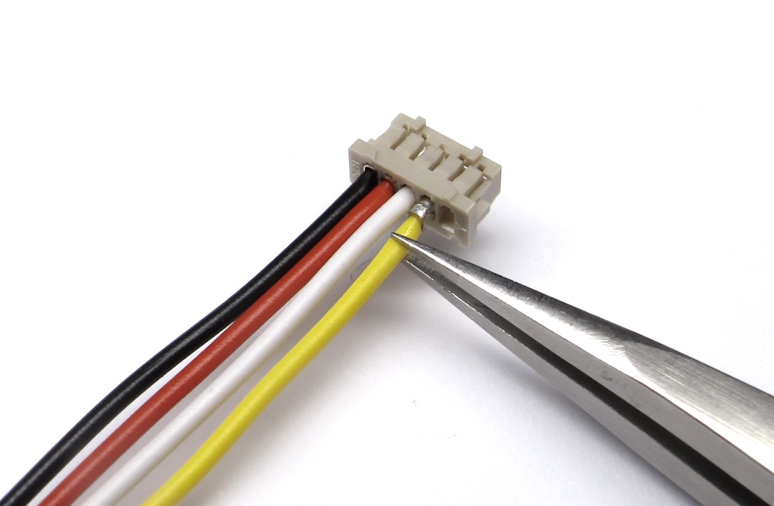
*[Instructions Crimping the Encoder Connectors](details_encoder_preparation.md#crimping-hirose-connector)*
*The actuator module assembly is now completed.
The next step is to test the module and determine the correct order of the motor phases.
Weight of the actuator module with 30cm wires: 160g*
---
## Step-by-Step Instructions
| Motor Preparation | Motor Shaft Preparation | Encoder Preparation |Center Pulley Preparation|
| --- | --- | --- | --- |
|  | |
| |  |
| |
| Output Pulley Preparation | Shell Preparation | Actuator Module Assembly |Actuator Module Testing|
| --- | --- | --- | --- |
|
|
| Output Pulley Preparation | Shell Preparation | Actuator Module Assembly |Actuator Module Testing|
| --- | --- | --- | --- |
|  |
|  |
|  |
| |
---
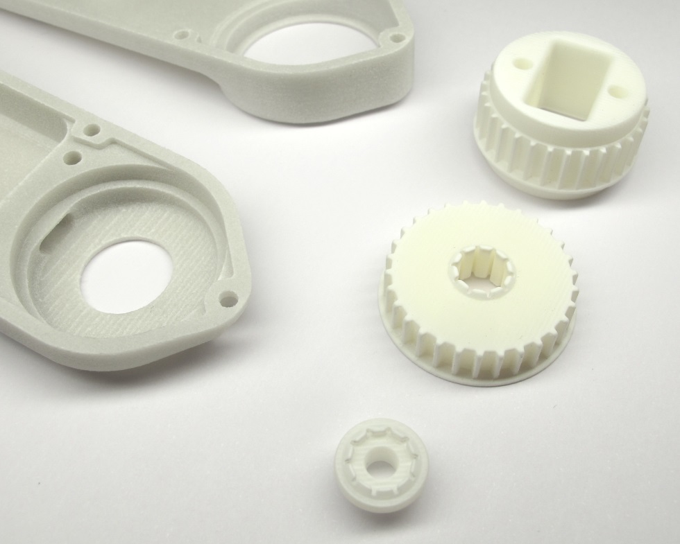
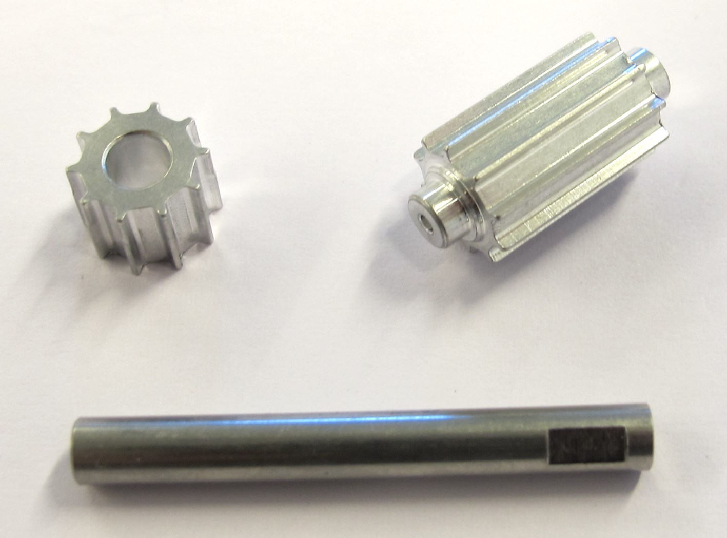
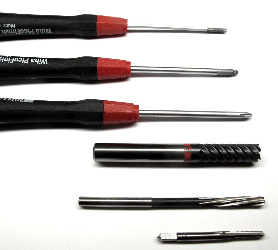
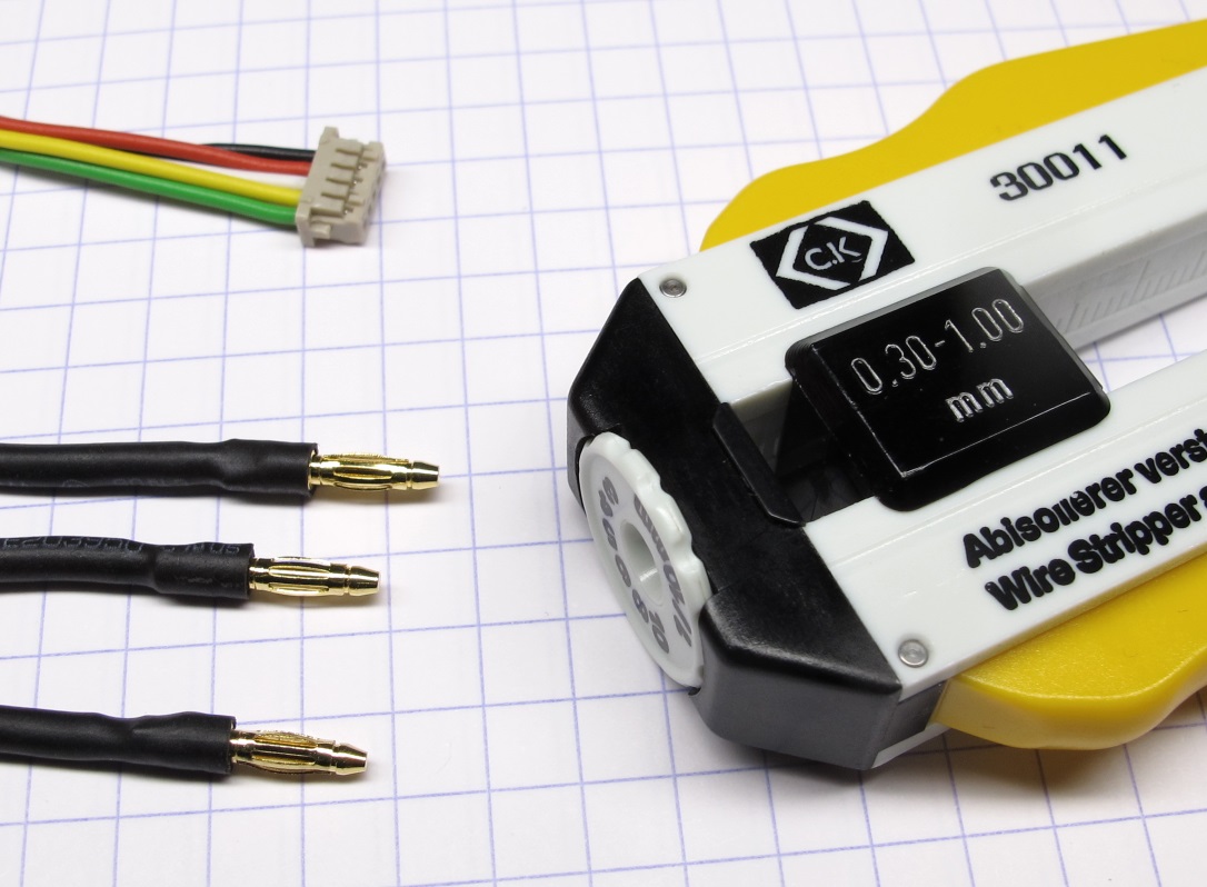
## More Details
| Details 3d Printed Parts | Details Machined Parts | Mechanical Tools and Consumables |Electronic Components and Tools|
| --- | --- | --- | --- |
|
|
---
## More Details
| Details 3d Printed Parts | Details Machined Parts | Mechanical Tools and Consumables |Electronic Components and Tools|
| --- | --- | --- | --- |
| |
| |
| |
| |
---
## More Information
[Open Dynamic Robot Initiative - Webpage](https://open-dynamic-robot-initiative.github.io)
[Open Dynamic Robot Initiative - YouTube Channel](https://www.youtube.com/channel/UCx32JW2oIrax47Gjq8zNI-w)
[Open Dynamic Robot Initiative - Forum](https://odri.discourse.group/categories)
[Open Dynamic Robot Initiative - Paper](https://arxiv.org/pdf/1910.00093.pdf)
[Hardware Overview](../../../README.md#open-robot-actuator-hardware)
[Software Overview](https://github.com/open-dynamic-robot-initiative/open-dynamic-robot-initiative.github.io/wiki)
[Back to Actuator Module](../README.md)
[Back to Top of Page](#details-actuator-module-assembly)
---
## Authors
Felix Grimminger
## License
BSD 3-Clause License
## Copyright
Copyright (c) 2019-2020, Max Planck Gesellschaft and New York University
|
---
## More Information
[Open Dynamic Robot Initiative - Webpage](https://open-dynamic-robot-initiative.github.io)
[Open Dynamic Robot Initiative - YouTube Channel](https://www.youtube.com/channel/UCx32JW2oIrax47Gjq8zNI-w)
[Open Dynamic Robot Initiative - Forum](https://odri.discourse.group/categories)
[Open Dynamic Robot Initiative - Paper](https://arxiv.org/pdf/1910.00093.pdf)
[Hardware Overview](../../../README.md#open-robot-actuator-hardware)
[Software Overview](https://github.com/open-dynamic-robot-initiative/open-dynamic-robot-initiative.github.io/wiki)
[Back to Actuator Module](../README.md)
[Back to Top of Page](#details-actuator-module-assembly)
---
## Authors
Felix Grimminger
## License
BSD 3-Clause License
## Copyright
Copyright (c) 2019-2020, Max Planck Gesellschaft and New York University