# Details Motor Preparation

*Starting Point: Antigravity 4004 300kV from T-Motor*

*End Result: Stator and rotor separated and prepared for installation*
## Description
* this page describes how to prepare the the outrunner motor for the brushless actuator modules
* stator and rotor are separated -> [Separating Rotor and Stator](#separating-rotor-and-stator)
* the motor shaft is removed from the rotor -> [Removing the Motor Shaft](#removing-the-motor-shaft)
* the bore diameter of the rotor is increased to fit the custom motor shaft -> [Increasing the Rotor Bore Diameter](#increasing-the-rotor-bore-diameter)
* the motor phase insulation is removed -> [Removing the Motor Phase Insulation](#removing-the-motor-phase-insulation)
* the motor phase wires are shortened and prepared -> [Preparing the Motor Phase Wires](#preparing-the-motor-phase-wires)
* the extension wires are soldered to the motor phase wires -> [Soldering the Extension Wires](#soldering-the-extension-wires)
* finally the motor phase connectors are soldered to the extension wires. -> [Soldering the Motor Phase Connectors](#soldering-the-motor-phase-connectors)
---
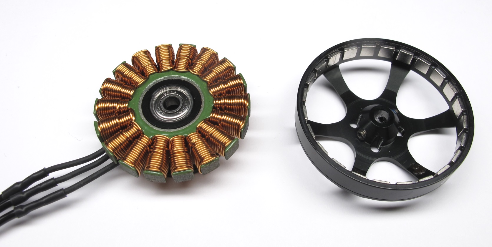
## Separating Rotor and Stator
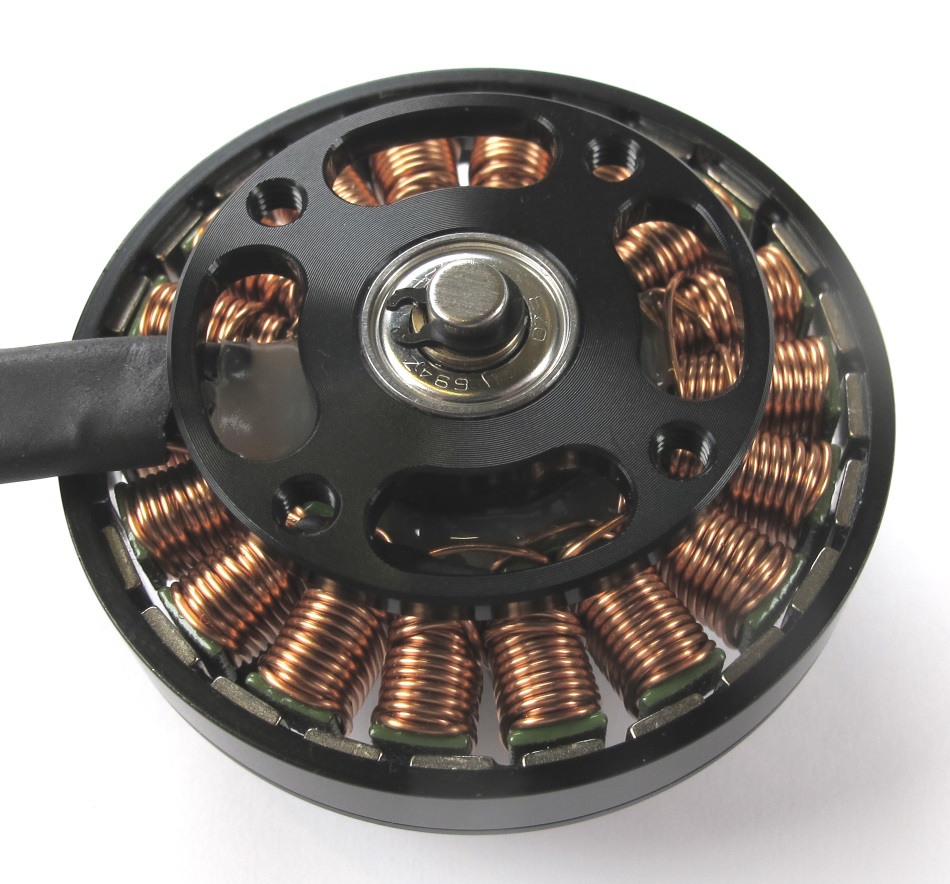
*Bottom view: the retaining ring holds the motor shaft in place*
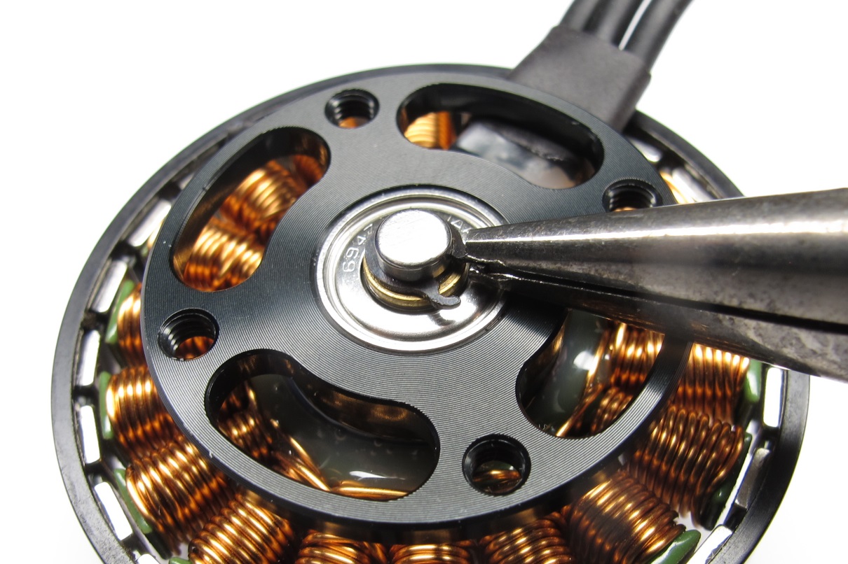
*Remove the retaining ring from the motor shaft using small pliers.
Don't worry about damaging the retaining ring - it's no longer needed*
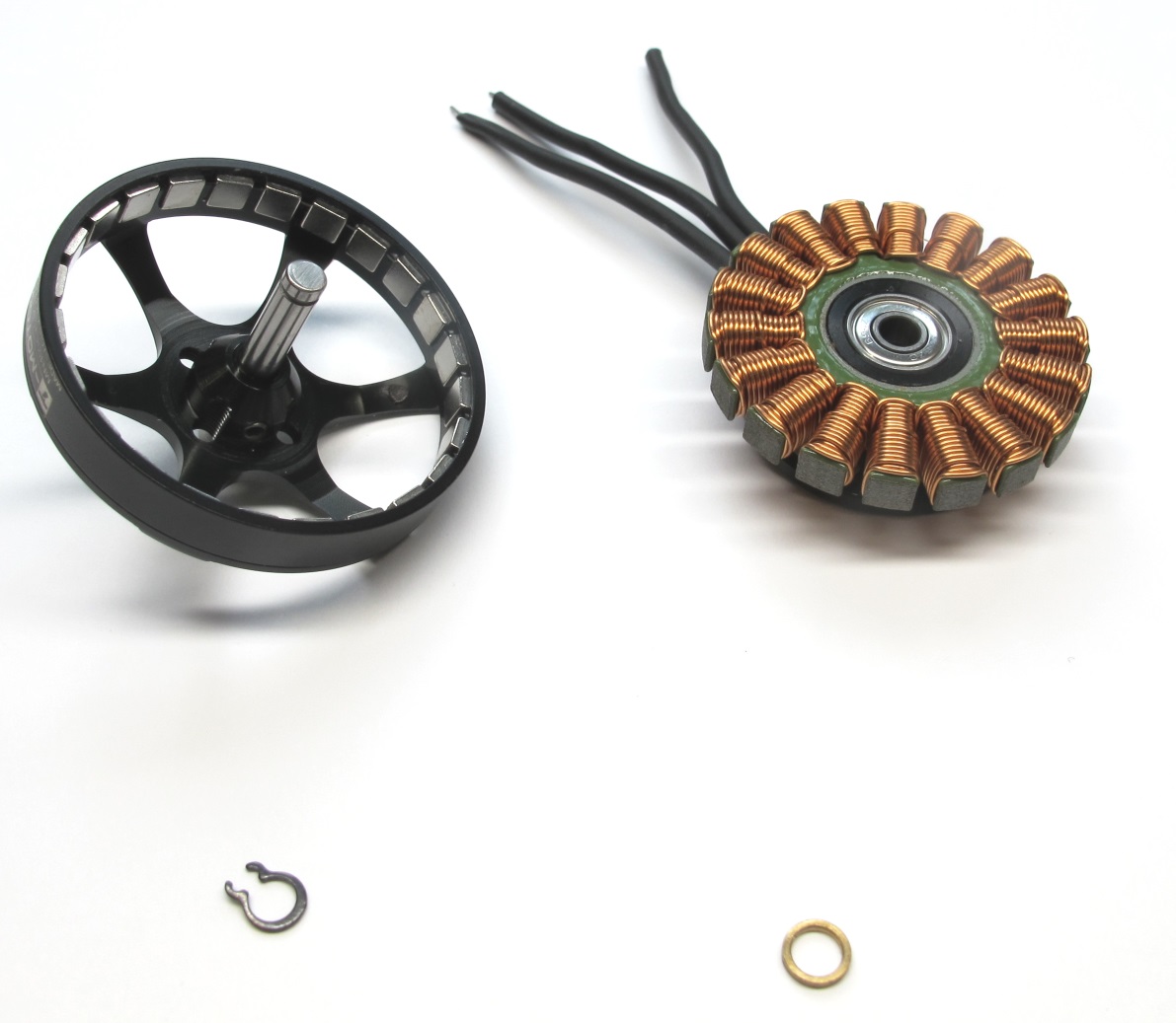
*Separate the rotor from the stator by pulling gently to overcome the magnetic forces..
Make sure to keep the brass washer. Store the rotor on a clean surface.
Metal particles will stick to the magnets and can cause problems later.*
---
## Rotor Preparation
### Removing the Motor Shaft

*Remove the two M3 set screws on the rotor using a 1,5mm hex driver.*

*Keep the set screws for reassembly.*

*For the next step you will need a hammer, pin driver
and the 3d printed "motor shaft extraction tool".
[-> STL file Motor Shaft Extraction Tool](../stl_files/tool_motor_shaft_extraction.STL)*

*Place the rotor on the "motor shaft extraction tool".*

*Use the hammer and pin driver to remove the motor shaft.*

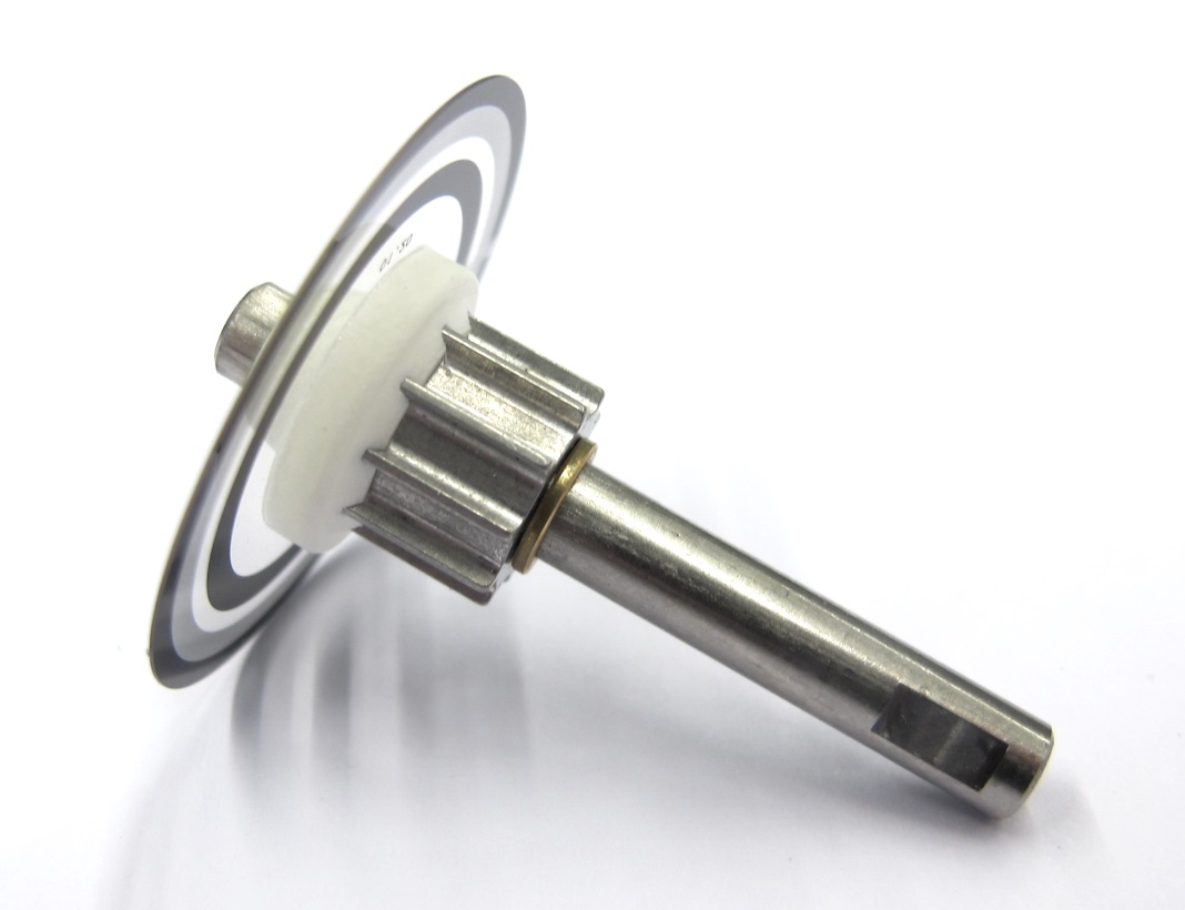
*Rotor with motor shaft removed.*
### Increasing the Rotor Bore Diameter

*You will now need different reamer sizes to increase the bore diameter of the rotor.
We use reamers with 3.98mm, 3.99mm and 4.00mm diameter.*

*Use a tool holder to manually increase the bore diameter.*

*Start with the smallest reamer - 3.98mm.
Put some oil on the reamer.
Carefully insert and turn the reamer a couple of times.*

*Put a bit of oil on the custom motor shaft.
[ -> PDF Drawing Custom Motor Shaft](../drawings/motor_shaft.PDF)*

*Try to insert the custom motor shaft.
If the reamed hole is too tight repeat the last two steps with the same reamer size.
If the bore is still too tight use the next larger reamer size.
Continue until the shaft can be installed and removed with moderate force.*
**Important:** Be careful not to increase the bore diameter too much.
If the fit is too loose the rotor will wobble when spinning.

*Install the two M3 set screws half way using a 1,5mm hex driver.*

*The rotor is now ready for assembly.*
---
## Stator Preparation
### Removing the Motor Phase Insulation
*Stator with original phase wires*
*Carefully cut and remove the large heat shrink at the base.*

*Cut off a piece of the phase wire heat shrink under an angle.*

*Hold the phase wire with pliers and grab the heat shrink with your fingers.*

*Slowly pull on the wire while holding the heat shrink.
The wire will cut through the heat shrink.*

*Continue until the insulation is removed half way.*

*You should now be able to carefully pull off the heat shrink from the phase wires.*

*Stator with insulation removed.*
### Preparing the Motor Phase Wires

*Don't shorten the motor phase wires for the Hip AA Actuator Modules - skip this step and continue with applying heat shrink to the wires.
For the Hip FE and Upper Leg Modules we shorten the motor phase wires to about 3cm measured from the base of the stator.
This helps to keep the solder connection inside of the shell structure.*

*We use a temperature controlled soldering iron to burn off the orange insulation.
Set your soldering iron to a temperature of abour 400 degrees celcius.*

*Put solder on the tip and heat up the ends of the phase wires.
Wait until the insulation disappears and you can see 5mm of silver wire exposed.*

*Motor phase wires with insulation removed from the ends.*

*Prepare thin heat shrink for the phase wires.*

*Apply the heat shrink using a heat gun.
You can now solder the extension wires.*
### Soldering the Extension Wires

*Reduce the soldering temperature to about 300 degrees celcius*

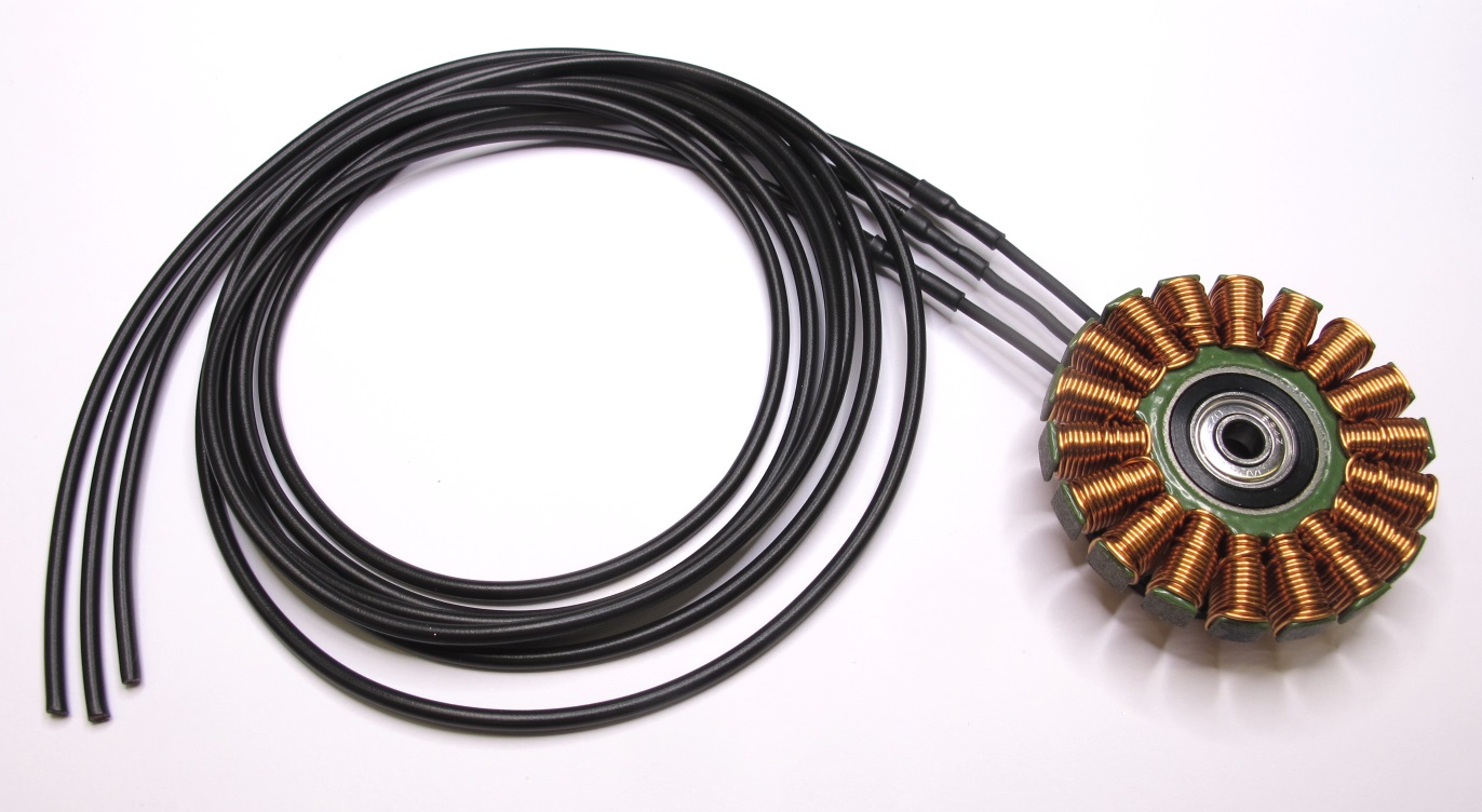
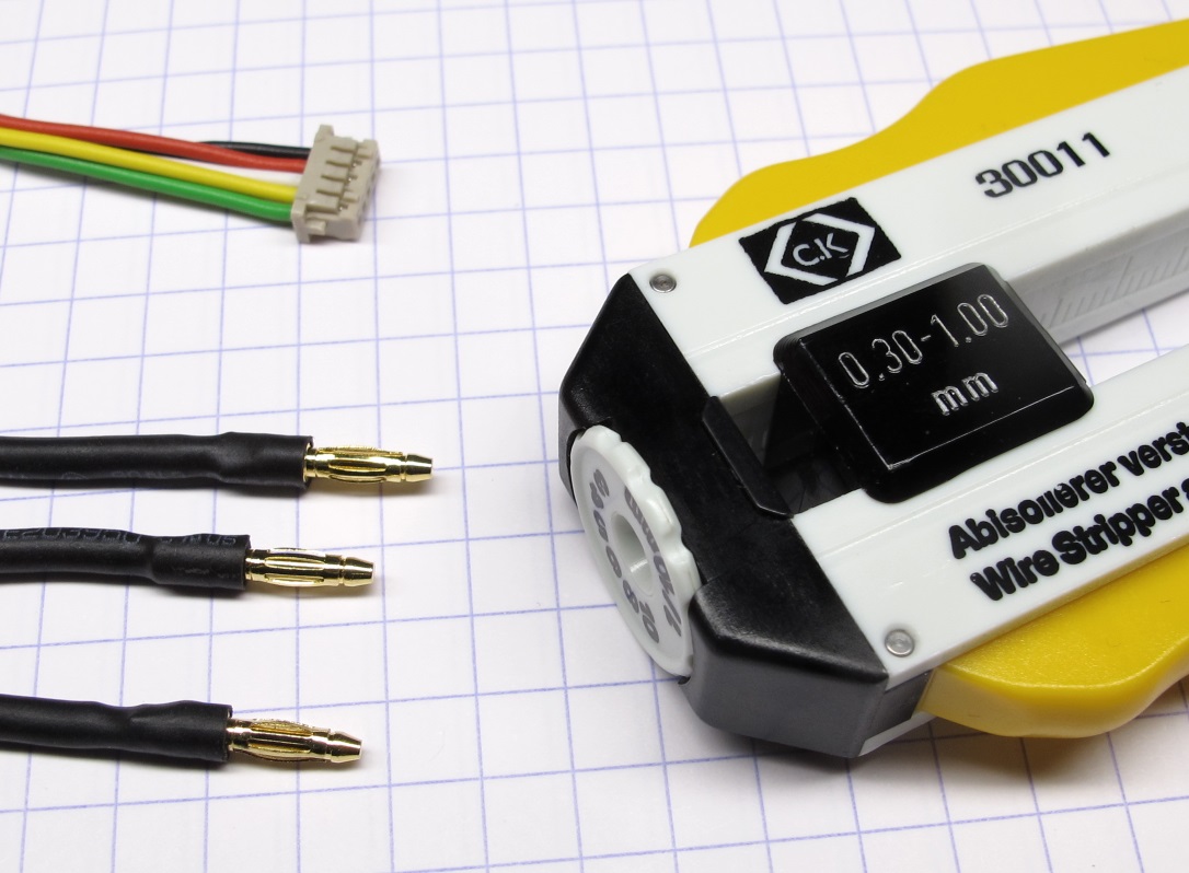
*Pepare the extension wires - make them a couple of cm longer than needed.
We use LiY wire with a cross section of 0,5mm 2.*

*Solder the extension wires to the phase wires.*

*Prepare the heat shrink for insulating the wires.
Try to keep the heat shrink short.*

*Use a heat gun to apply the heat shrink.*
*If you are unsure about the correct wire length you can stop here.
Follow all the other preparation steps and fully assemble the actuator module.
You can then determine the correct wire length and solder the connectors later.*
### Soldering the Motor Phase Connectors

*If you know the required wire length cut the wires accordingly.
Remove a bit of the insulation, twist the strands and apply solder.*
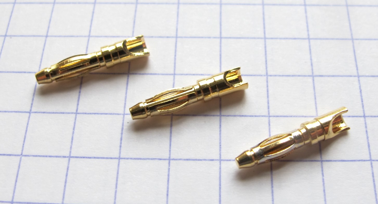
*Prepare the male motor phase connectors.
We are using the 2mm gold connectors from REELY*

*Solder the connectors onto the phase wires.*

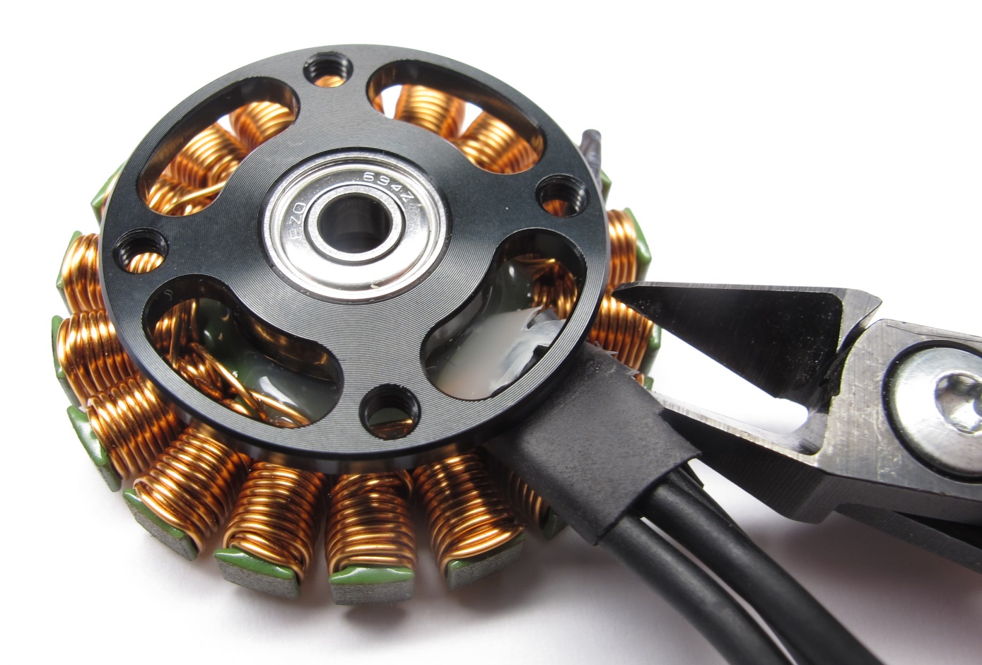
*Prepare heat shrink for the connectors.
It makes it easier to align the heat shrink if you install the mating connectors.*

*Install the mating connectors.*

*Align the heat shrink and apply it using a heat gun.*

*Finished motor phase connnectors.*

*The stator is now ready for assembly.*
---
## Step-by-Step Instructions
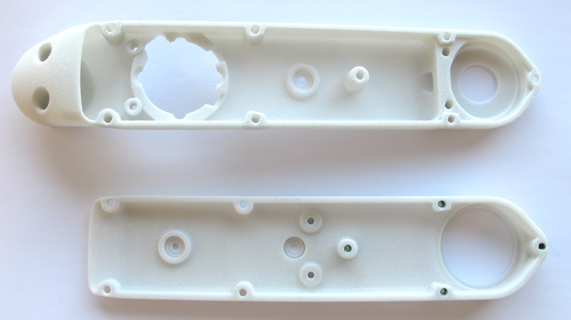
| Motor Preparation | Motor Shaft Preparation | Encoder Preparation |Center Pulley Preparation|
| --- | --- | --- | --- |
|  |
|  |
|  |
| |
| Output Pulley Preparation | Shell Preparation | Actuator Module Assembly |Actuator Module Testing|
| --- | --- | --- | --- |
|
|
| Output Pulley Preparation | Shell Preparation | Actuator Module Assembly |Actuator Module Testing|
| --- | --- | --- | --- |
|  |
|  |
| 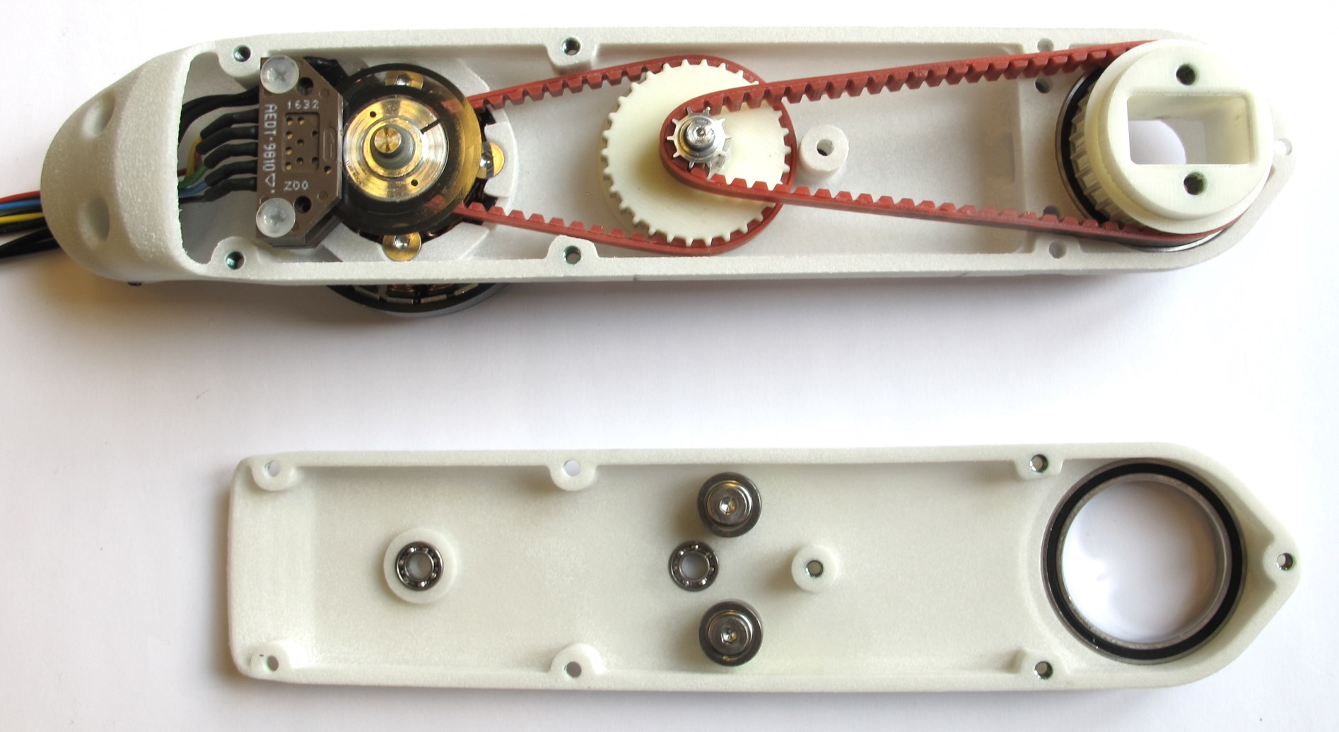 |
| |
---
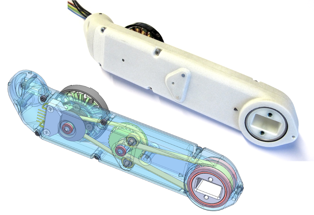
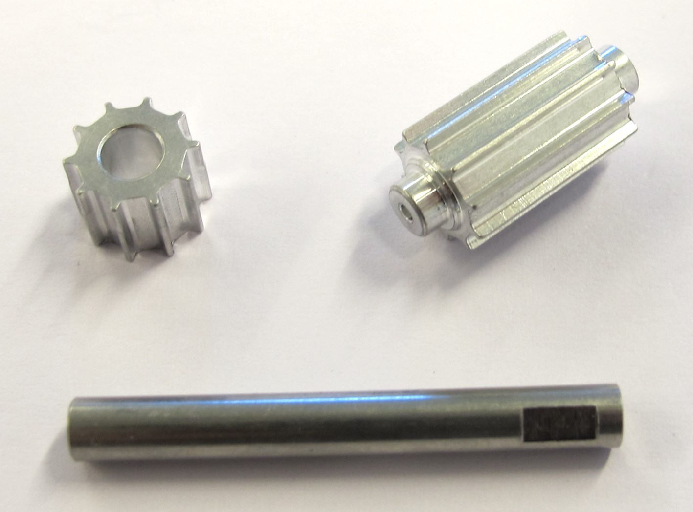
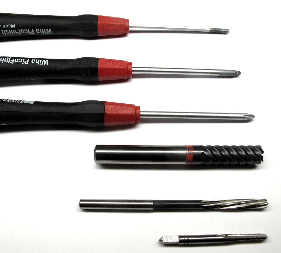
## More Details
| Details 3d Printed Parts | Details Machined Parts | Mechanical Tools and Consumables |Electronic Components and Tools|
| --- | --- | --- | --- |
|
|
---
## More Details
| Details 3d Printed Parts | Details Machined Parts | Mechanical Tools and Consumables |Electronic Components and Tools|
| --- | --- | --- | --- |
|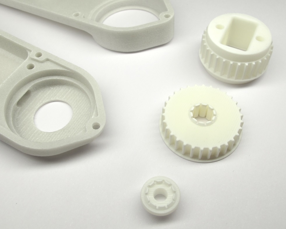 |
| |
| |
| |
---
## More Information
[Open Dynamic Robot Initiative - Webpage](https://open-dynamic-robot-initiative.github.io)
[Open Dynamic Robot Initiative - YouTube Channel](https://www.youtube.com/channel/UCx32JW2oIrax47Gjq8zNI-w)
[Open Dynamic Robot Initiative - Forum](https://odri.discourse.group/categories)
[Open Dynamic Robot Initiative - Paper](https://arxiv.org/pdf/1910.00093.pdf)
[Hardware Overview](../../../README.md#open-robot-actuator-hardware)
[Software Overview](https://github.com/open-dynamic-robot-initiative/open-dynamic-robot-initiative.github.io/wiki)
[Back to Actuator Module](../README.md)
[Back to Top of Page](#details-motor-preparation)
---
## Authors
Felix Grimminger
## License
BSD 3-Clause License
## Copyright
Copyright (c) 2019-2020, Max Planck Gesellschaft and New York University
|
---
## More Information
[Open Dynamic Robot Initiative - Webpage](https://open-dynamic-robot-initiative.github.io)
[Open Dynamic Robot Initiative - YouTube Channel](https://www.youtube.com/channel/UCx32JW2oIrax47Gjq8zNI-w)
[Open Dynamic Robot Initiative - Forum](https://odri.discourse.group/categories)
[Open Dynamic Robot Initiative - Paper](https://arxiv.org/pdf/1910.00093.pdf)
[Hardware Overview](../../../README.md#open-robot-actuator-hardware)
[Software Overview](https://github.com/open-dynamic-robot-initiative/open-dynamic-robot-initiative.github.io/wiki)
[Back to Actuator Module](../README.md)
[Back to Top of Page](#details-motor-preparation)
---
## Authors
Felix Grimminger
## License
BSD 3-Clause License
## Copyright
Copyright (c) 2019-2020, Max Planck Gesellschaft and New York University