# Details Output Pulley Preparation
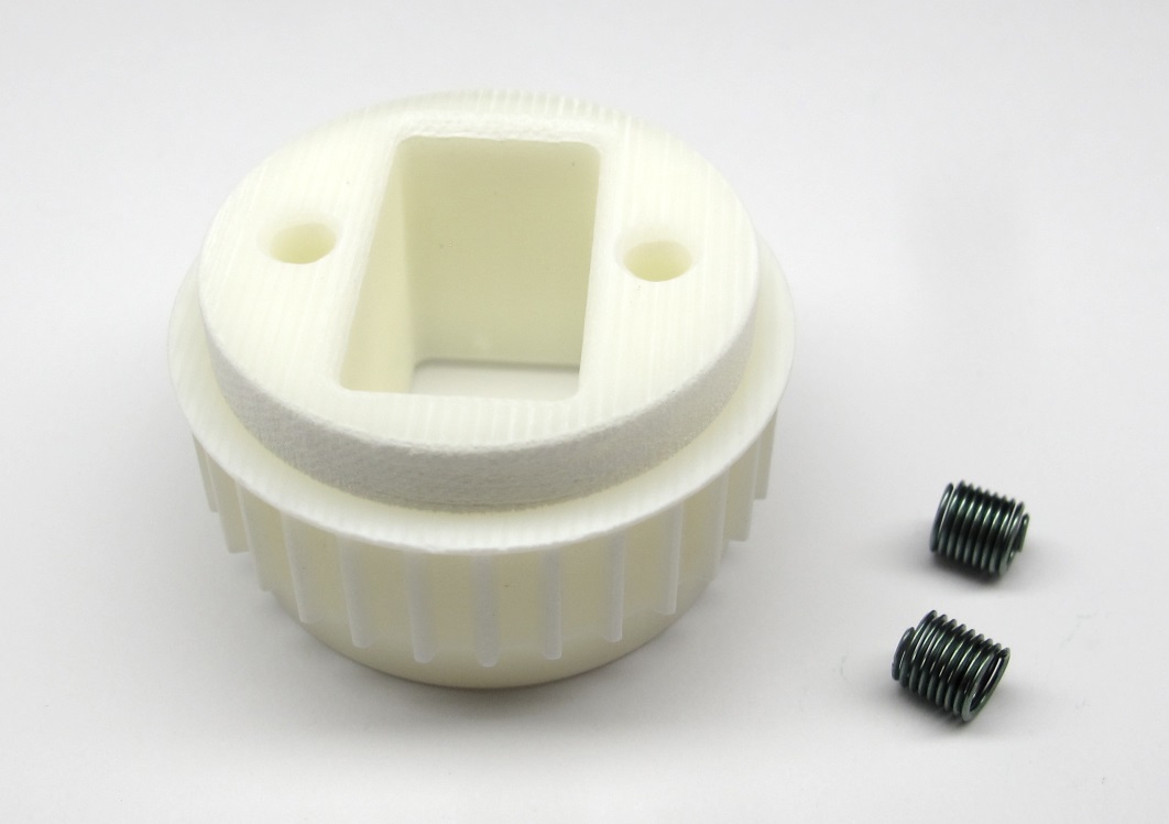
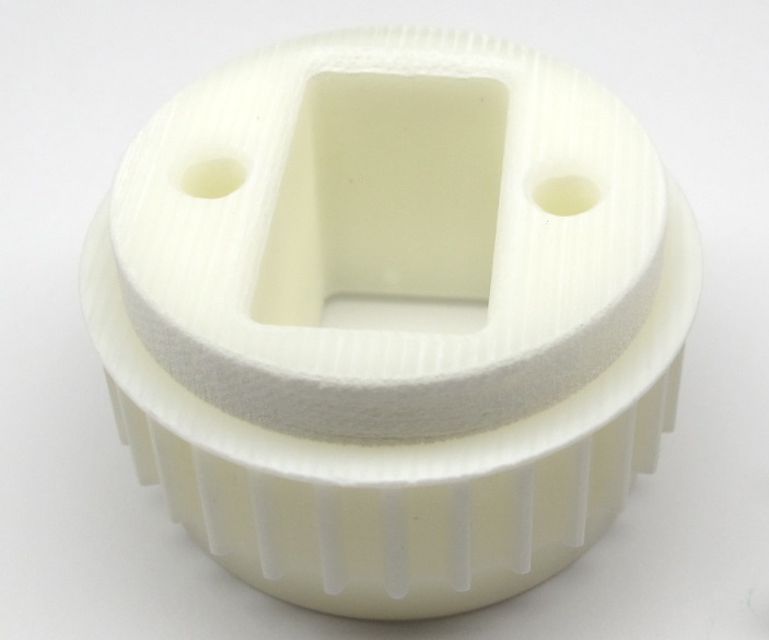
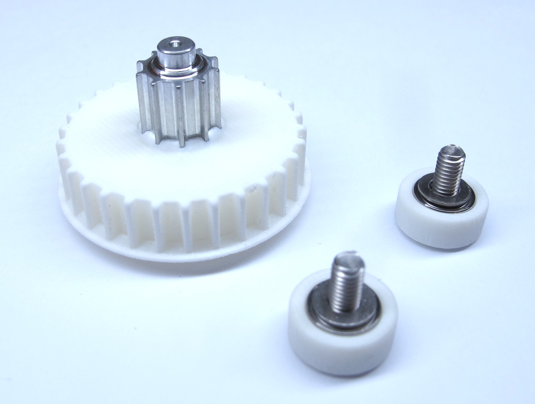
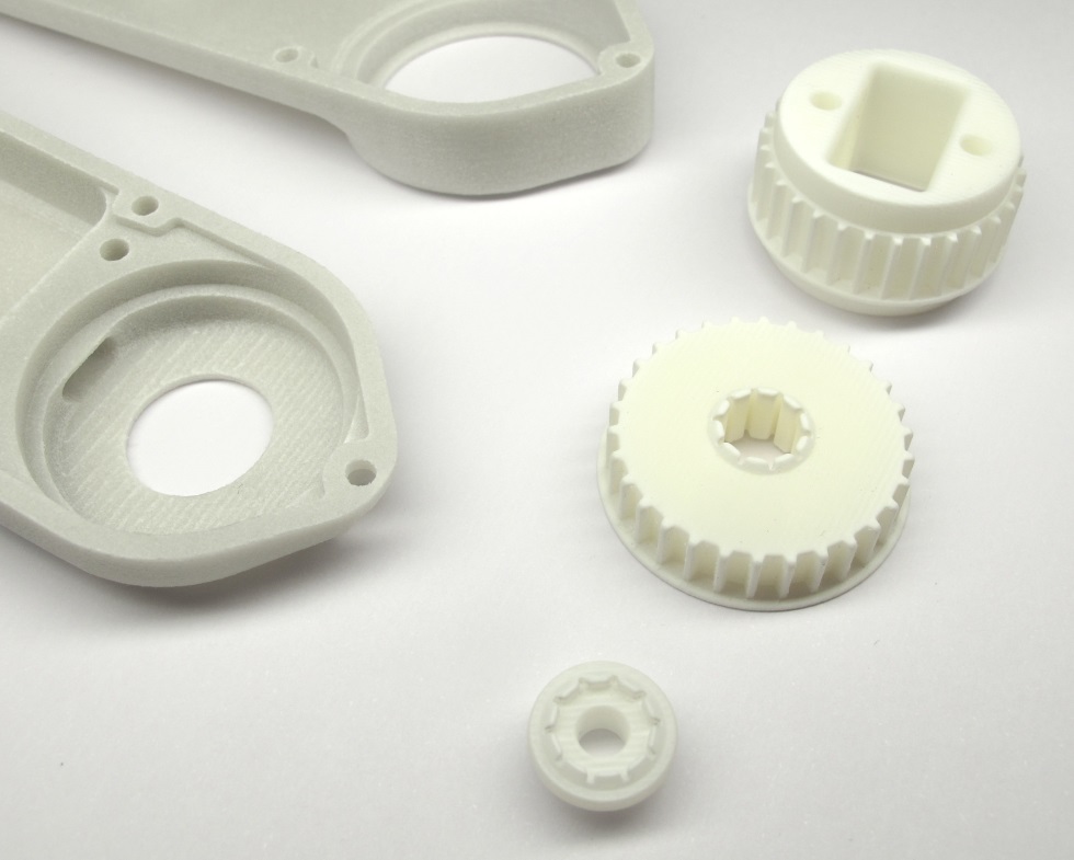
*Starting Point: Output pulley and M3 Helicoil Inserts.*
*End Result: Output pulley prepared for installation.*
## Description
* this page describes how to prepare the output pulley for the brushless actuator modules
* the shaft diameters of the output pulley are adjusted to fit the bearings
[-> Adjusting the Output Shaft Diameters](#adjusting-the-output-shaft-diameters)
* two Helicoil thread inserts are installed in the mounting holes of the output pulley
[-> Installing Helicoil Thread Inserts](#installing-helicoil-thread-inserts)
* **Exeception:** If you are preparing an output pulley for a Hip AA actuator module the helicoils shouldn't be installed
[-> Pulley for Hip AA Actuator Module](#pulley-for-hip-aa-actuator-module)
### More Information
* More information 3d printing: [Details 3d Printed Parts](details_3d_printed_parts.md#details-3d-printed-parts)
* [STL File - Output Pulley](../stl_files/transmission_pulley_at3_t30_output.STL)
## Adjusting the Output Shaft Diameters
The dimensions of 3d printed parts can vary quite a bit depending on the printer, the printing technology and the material.
That's why we print the diameters that has to fit the bearings a bit oversize and machine the part to the right diameter on a lathe.
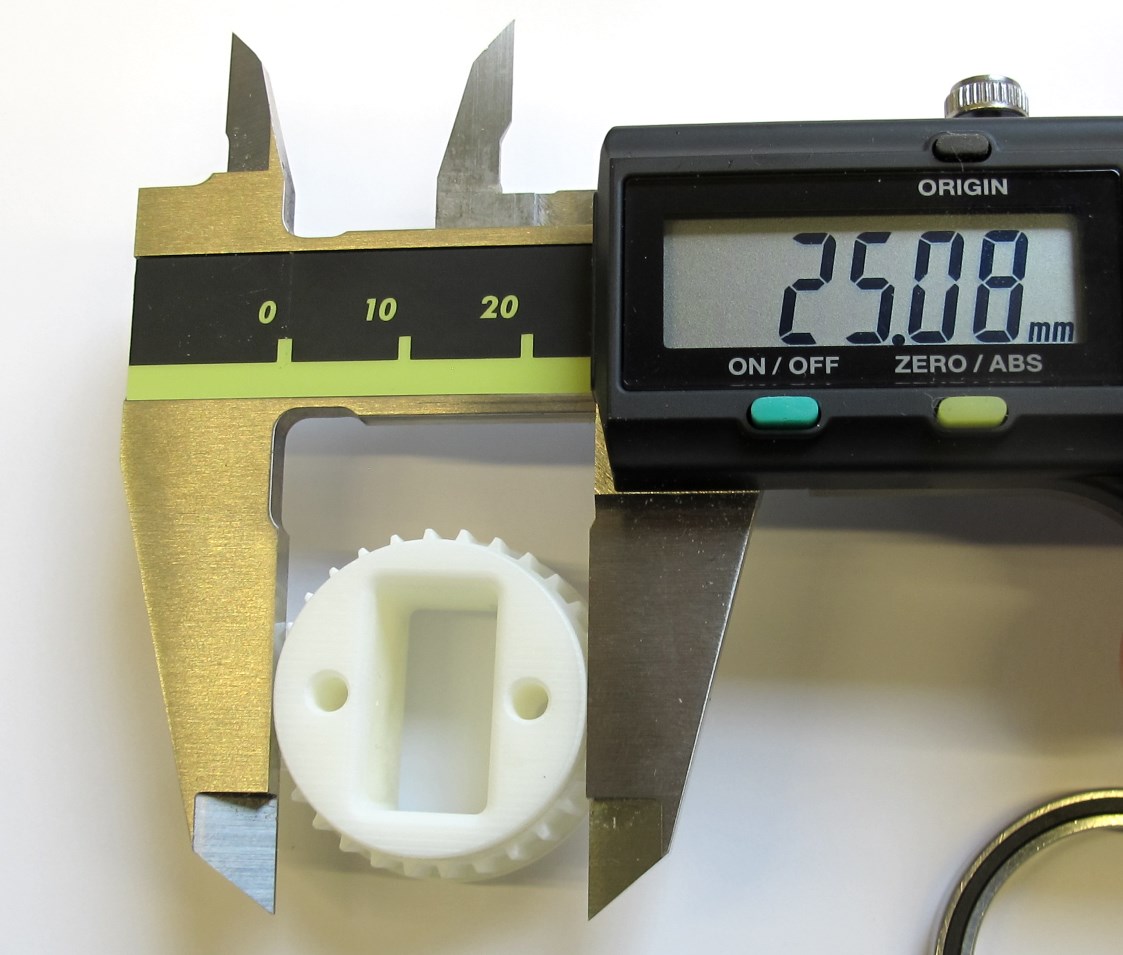
*Output pulley - oversized diameter.*
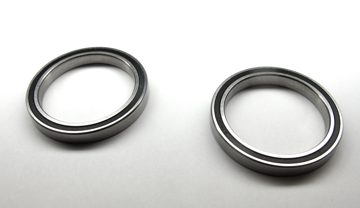
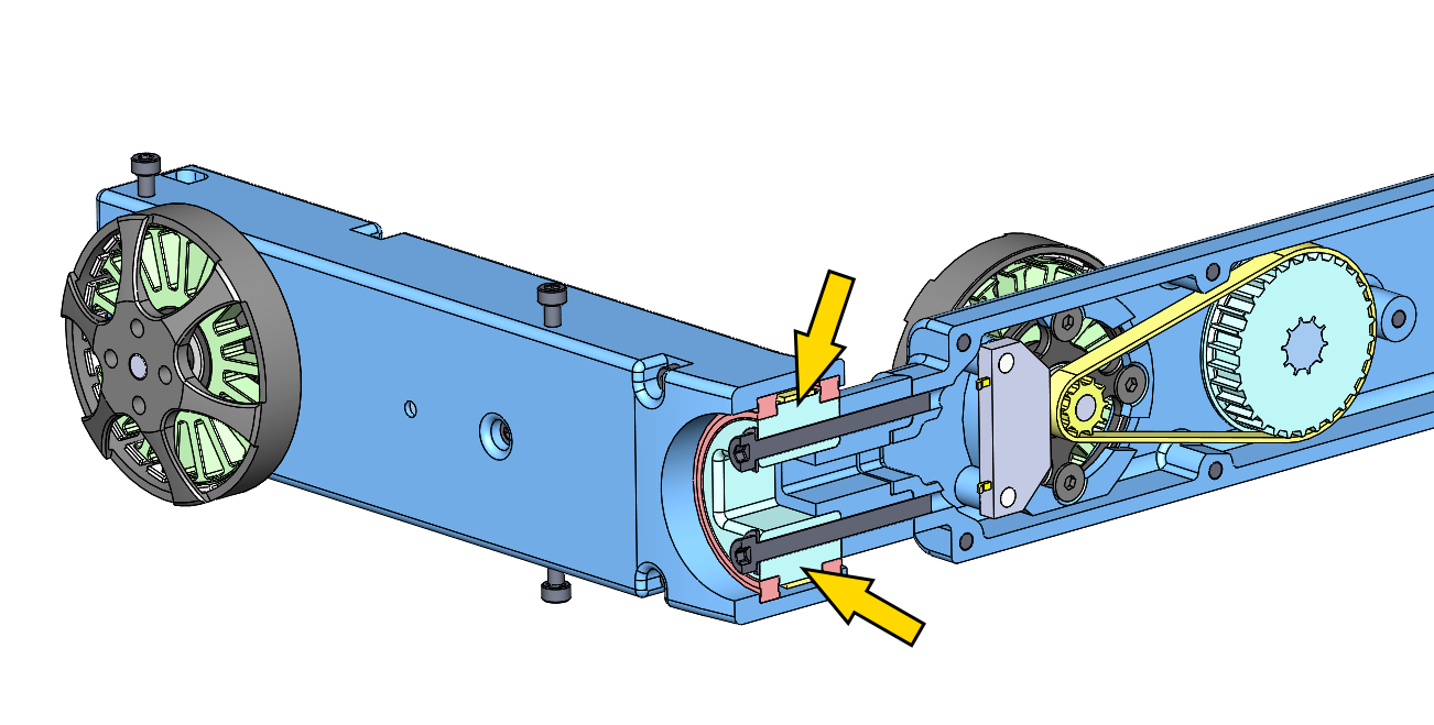
*Output bearings - dimensions: 32mm x 25mm x 4mm.*

*A 25mm collet helps with clamping the output pulley.*
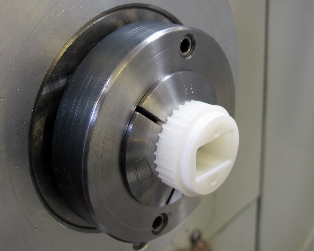
*Place the pulley on the lathe and clamp gently on one of the output shafts.*

*Use a cutting tool with a sharp edge.*

*Reduce the shaft diameter in small steps and check the fit with the output bearing.*

*There should be a light press-fit between the bearing and the pulley.
You should be able to install and remove the bearing by hand with moderate force.
When the diameter is correct - turn the pulley around and repeat the same steps for the opposite side.*
---
## Pulley for Hip AA Actuator Module
*Exception: Hip AA Output Pulley - the fasteners go through the pulley.*
* the pulley for the Hip AA actuator modules is an exception
* since the fasteners go through the pulley the helicoils mustn't be installed
* increase the hole diameters to 3mm and don't install the Helicoil thread inserts
*Put a small chamfer on the mounting holes.*
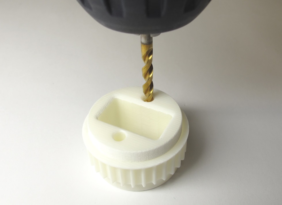
*Increase the diameter of the mounting holes using a 3mm drill bit.*
*The Hip AA Output Pulley is now ready for installation.*
**If you are preparing a Hip AA output pulley you should stop here and ignore all the following steps.**
---
## Installing Helicoil Thread Inserts
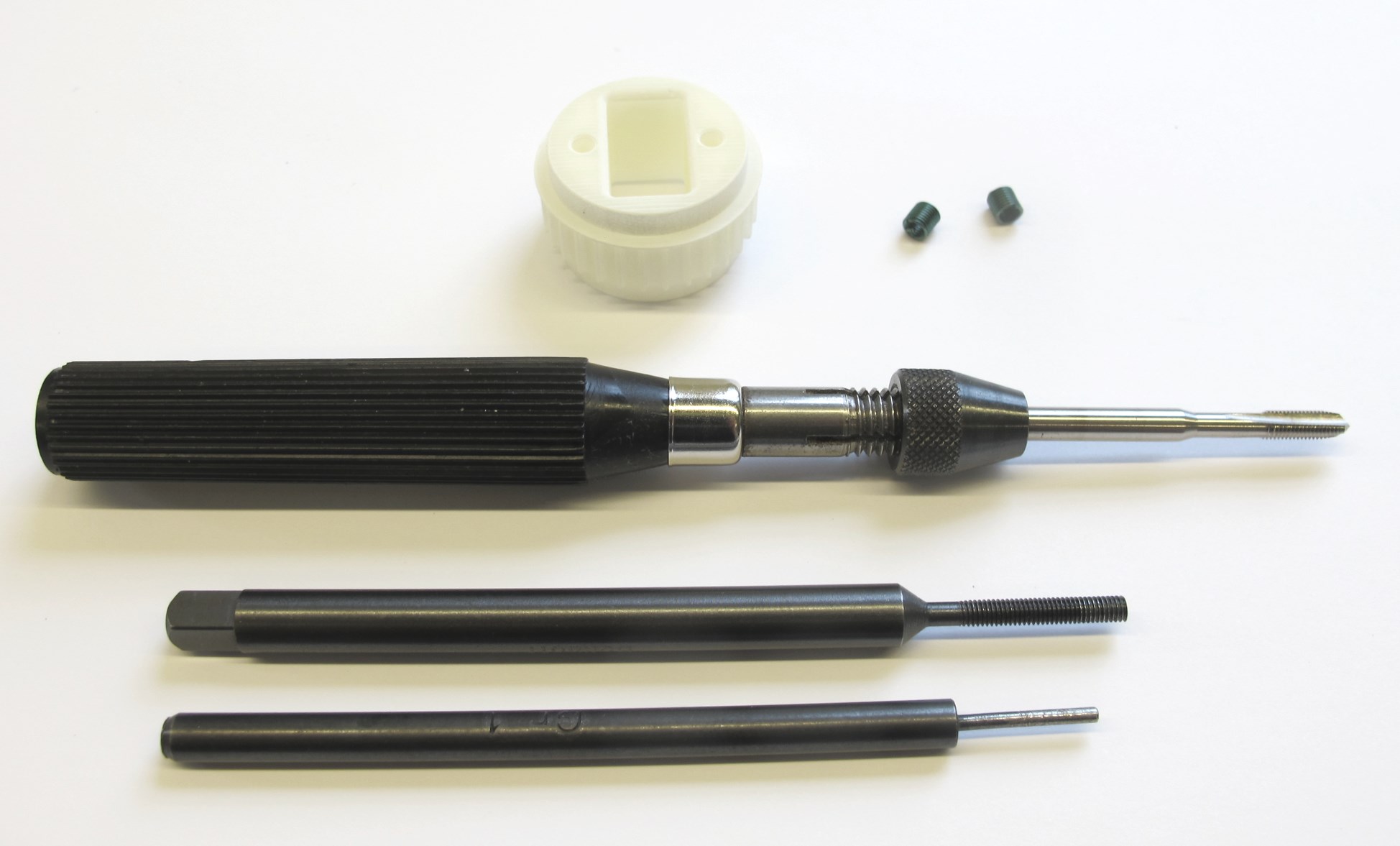
*Output Pulley, M3 Helicoils and Helicoil Tools.*
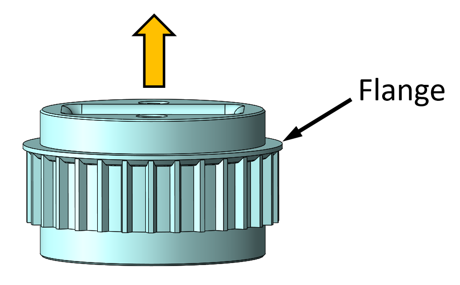
*Make sure that the flange on the pulley faces upwards for all of the following steps.*
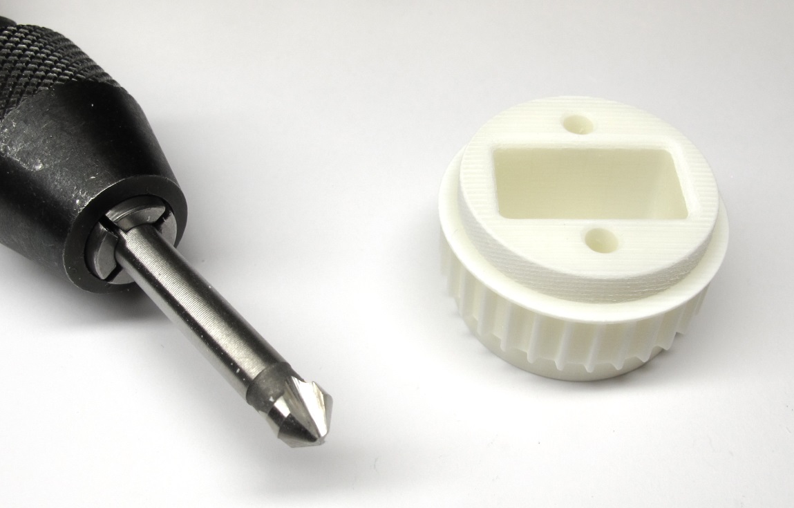
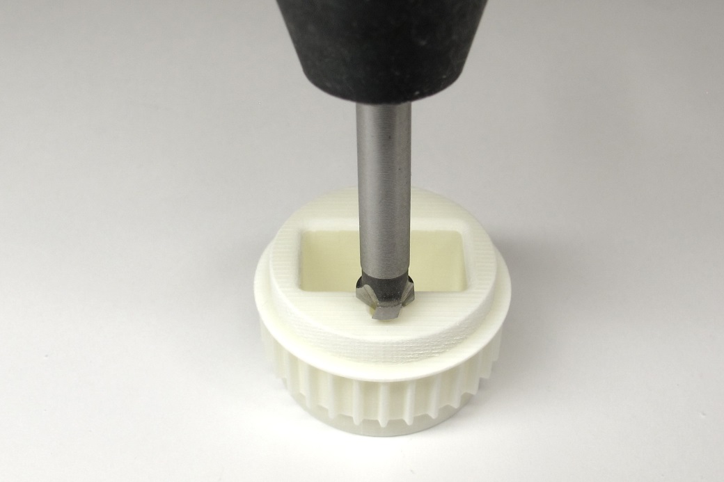
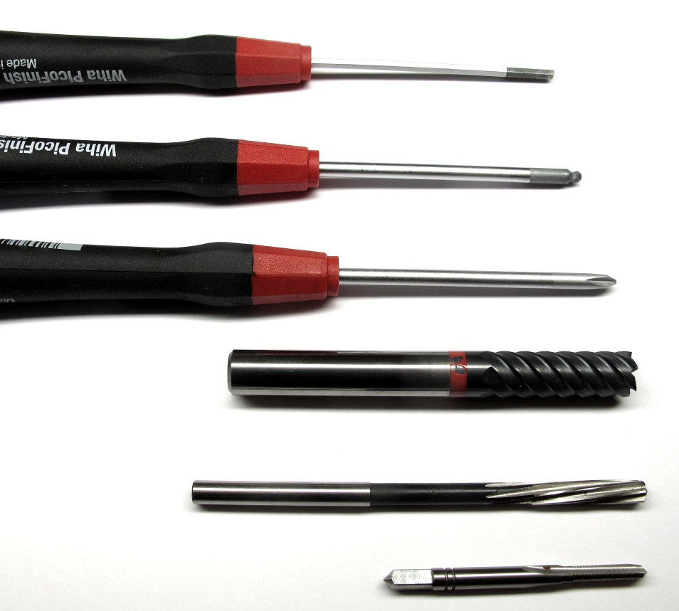
*45 degree chamfer tool and output pulley.*
*Put a small chamfer on the mounting holes.*
*The holes should have a diameter of about 2,9mm.
Drill through with a 3mm drill bit.
Drill with
increasing drill diameters in steps of 0,1mm.
Increase the diameter of the holes until you reach a diameter of 3.3mm.*
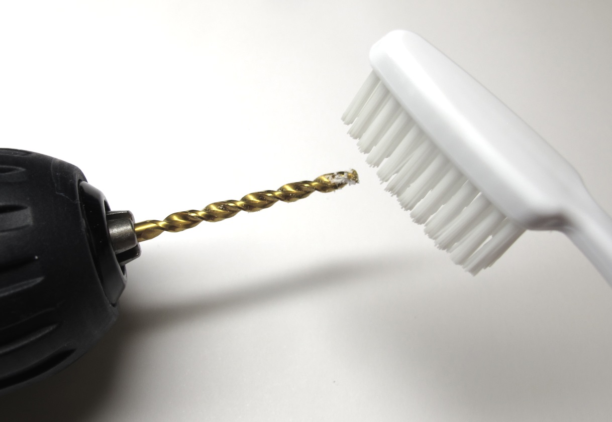
*Clean the drill with a tooth brush if required.*
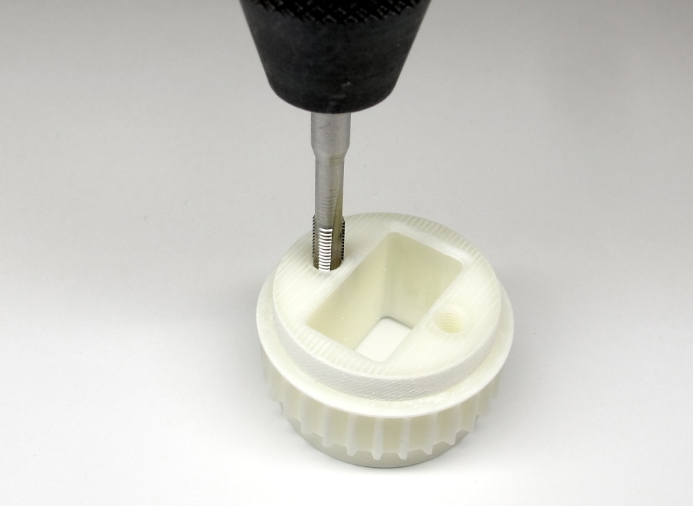
*Tap both holes using the Helicoil M3 tap.
The flange on the pulley has to point upwards as shown in the picture.*

*If the resistance increases carefully back out the tap and clean it with a tooth brush.
Continue until the Helicoil thread is fully cut.*
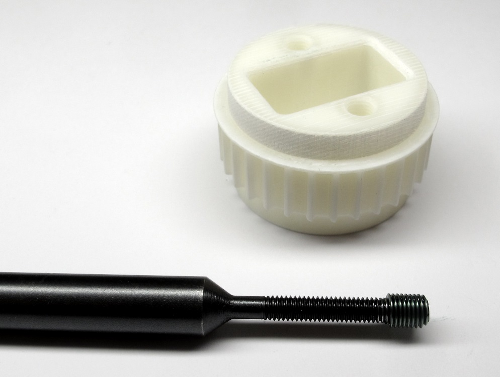
*Place a M3 Helicoil with a length of 6mm on the insertion tool.*
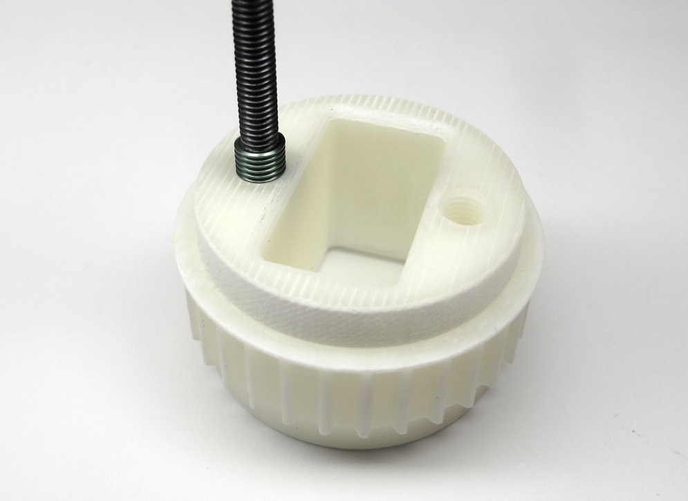
*Insert both Helicoils with the insertion tool.
Make sure that the end of the insert is about half a turn below the outer surface*
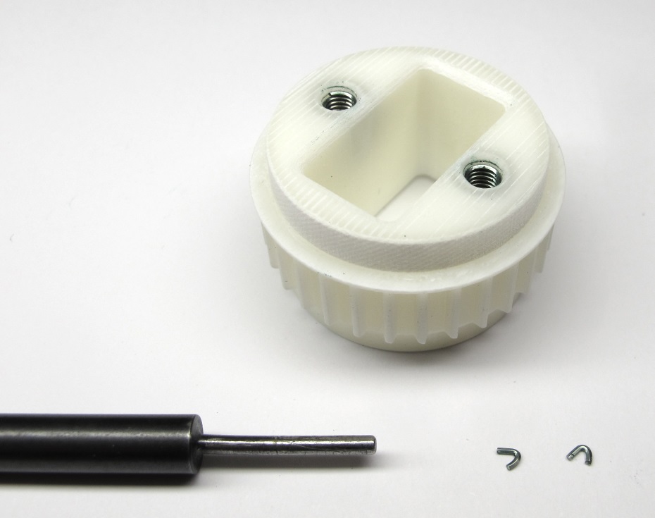
*Remove both tangs using the tang break-off tool.
Make sure that the tangs don't stay inside of the part.*
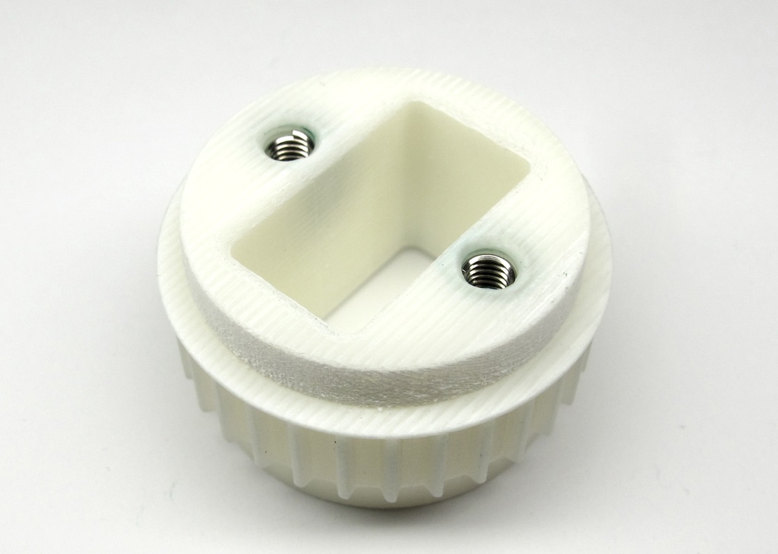
*The output pulley is now ready for installation.*
---
## Step-by-Step Instructions
| Motor Preparation | Motor Shaft Preparation | Encoder Preparation |Center Pulley Preparation|
| --- | --- | --- | --- |
|  |
|  |
|  |
| |
| Output Pulley Preparation | Shell Preparation | Actuator Module Assembly |Actuator Module Testing|
| --- | --- | --- | --- |
| |
|
| Output Pulley Preparation | Shell Preparation | Actuator Module Assembly |Actuator Module Testing|
| --- | --- | --- | --- |
| |  |
|  |
| |
---
## More Details
| Details 3d Printed Parts | Details Machined Parts | Mechanical Tools and Consumables |Electronic Components and Tools|
| --- | --- | --- | --- |
|
|
---
## More Details
| Details 3d Printed Parts | Details Machined Parts | Mechanical Tools and Consumables |Electronic Components and Tools|
| --- | --- | --- | --- |
| |
| |
| |
| |
---
## More Information
[Open Dynamic Robot Initiative - Webpage](https://open-dynamic-robot-initiative.github.io)
[Open Dynamic Robot Initiative - YouTube Channel](https://www.youtube.com/channel/UCx32JW2oIrax47Gjq8zNI-w)
[Open Dynamic Robot Initiative - Forum](https://odri.discourse.group/categories)
[Open Dynamic Robot Initiative - Paper](https://arxiv.org/pdf/1910.00093.pdf)
[Hardware Overview](../../../README.md#open-robot-actuator-hardware)
[Software Overview](https://github.com/open-dynamic-robot-initiative/open-dynamic-robot-initiative.github.io/wiki)
[Back to Actuator Module](../README.md)
[Back to Top of Page](#details-output-pulley-preparation)
---
## Authors
Felix Grimminger
## License
BSD 3-Clause License
## Copyright
Copyright (c) 2019-2020, Max Planck Gesellschaft and New York University
|
---
## More Information
[Open Dynamic Robot Initiative - Webpage](https://open-dynamic-robot-initiative.github.io)
[Open Dynamic Robot Initiative - YouTube Channel](https://www.youtube.com/channel/UCx32JW2oIrax47Gjq8zNI-w)
[Open Dynamic Robot Initiative - Forum](https://odri.discourse.group/categories)
[Open Dynamic Robot Initiative - Paper](https://arxiv.org/pdf/1910.00093.pdf)
[Hardware Overview](../../../README.md#open-robot-actuator-hardware)
[Software Overview](https://github.com/open-dynamic-robot-initiative/open-dynamic-robot-initiative.github.io/wiki)
[Back to Actuator Module](../README.md)
[Back to Top of Page](#details-output-pulley-preparation)
---
## Authors
Felix Grimminger
## License
BSD 3-Clause License
## Copyright
Copyright (c) 2019-2020, Max Planck Gesellschaft and New York University